Electrically isolating the old tank bottom from a newly installed double bottom tank has been performed for decades. The entire old tank bottom, or portions thereof, have been removed or cut away and left in place to eliminate the electronic shield created by the old tank bottom relative to the new tank bottom. This is done to allow cathodic protection (CP) current to flow to the new tank bottom. The old tank bottom, after being electrically isolated from the new tank bottom, has even been used as an anode to protect the new tank bottom.1
A new method has been invented that does not require cutting into the tank and removing the old tank bottom or portions thereof and can be performed from outside the tank. Structural fiberglass angle or other nonconductive materials (or even a created air gap) can be inserted between the tank bottoms to allow for electrical isolation between the upper and lower tank bottoms. The electrical isolation material can be easily removed and replaced if damaged. The tank does not need to be internally cleaned and de-gassed to install the electrical isolation, which is a substantial savings to the owner. This method will benefit many tank owners/operators that have double bottomed tanks without a high-density polyethylene (nonconductive) liner between the old and new tank bottoms. Once the old tank bottom and dead shell are electrically isolated (out of electronic contact) away from the new (upper) tank bottom, CP current from conventional CP systems and/or deep anode beds will flow to the newer (upper) tank bottom providing CP.

On a current-day, double bottom tank without this new concept, CP current will flow to the lower tank bottom, with no CP benefit to the newer upper bottom (Figure 1). This method will work on new double bottom tanks with newly constructed sand tank pads as specified in NACE SP01932016,2 as well as existing double bottom tanks with existing sand pads. New or existing double bottom tanks resting on concrete pads or slabs can benefit from this new method, as CP currents will flow to the areas of the new tank bottom that are in electrolytic contact with the concrete. API 6533 internal inspection intervals can be extended by five years for adding CP. In all cases, once the old tank bottom is electrically isolated, the old tank bottom (lower bottom) becomes essentially transparent, allowing CP current to flow right through the old tank bottom to protect the new tank bottom. Nonconductive-type release prevention membranes were required to be used in the past between the old tank bottom and upper/new tank bottom to prevent the galvanic effects of new steel bottom/old steel bottom corrosion.3
A conductive type of release prevention barrier can now be utilized to provide leak prevention, without the concern of new steel bottom/old steel bottom galvanic corrosion occurring between the two tank bottoms. Significant advantages occur by electrically isolating the upper tank bottom from the old tank floor and dead shell from outside the tank on existing double bottom tanks. The very costly expense of cutting into the tank, removal of the old tank bottom, and perhaps contaminated soil is eliminated with this new method. The most significant advantage is that CP current can always pass through the old tank bottom, eliminating the problems and concerns of consumed CP systems between the tank bottoms.
New Double Bottom Tanks
If a new tank bottom has to be installed over an existing tank bottom, this new method can be provided prior to installing the new bottom to electrically isolate the old bottom and dead shell away from the new upper bottom. The recommended clean sand pad per NACE SP0193-2016, and a closely installed CP system with anodes between the tank bottoms can be used; and/or use your existing CP conventional or deep anode groundbeds to provide CP to the new tank bottom.
If a concrete pad is utilized, a layer of sand can be installed on top of the concrete pad in accordance with NACE SP0193-2016 section 5.7.1, to provide an improved path for CP current to flow to the tank bottom through the concrete pad. The new concept may also include the use of a conductive (clay) liner to be installed over the old tank bottom as a release prevention barrier (RPB), allowing CP current flow through the conductive liner, while protecting the environment. A conductive RPB may or may not be used in combination with the new method. The concern about depleted CP systems between the tank bottoms has been eliminated, as CP current can now flow through the old tank bottom to the new (upper) tank bottom indefinitely.
Electrically Isolated Tank Bottom Information and Test Data
Two existing double bottom tanks are presented showing the layout and CP data where the old tank bottom and portions of the dead shell were electrically isolated from the upper tank bottoms to allow CP currents to flow to the upper tank bottoms.
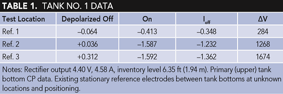
Tank No. 1
• Existing double bottom tank 85 ft (25.91 m) in diameter (Table 1).
— Diesel fuel operating at ambient temperatures
— Tank originally constructed as a double bottom tank
— Double bottom installed without a nonconductive RPB
— Constructed with an impressed current CP (ICCP) system between the tank bottoms
— CP system found to not be protecting tank in accordance with NACE criteria due to ICCP system trying to protect both tank bottoms
— A perimeter ICCP system was originally installed to provide CP to the lower tank bottom
— API 653 internal inspection revealed soil side corrosion on the upper tank bottom due to insufficient CP
— Next API 653 internal inspection interval would be reduced for lack of sufficient CP to five years
— Structural fiberglass angle was installed and secured under the upper tank bottom to electrically isolate the upper tank bottom from the dead shell and lower tank bottom (Figure 2)

Results of electrically isolating the upper tank bottom from the lower tank bottom and dead shell for Tank No. 1:
• CP in accordance with NACE SP0193-2016 criteria
• Existing CP system between tank bottoms now providing adequate CP
• Perimeter CP system current output decreased (not needed for upper tank bottom)
• Inspection interval extended to 10 years from five years
• $120,000 cleaning and inspection expenditure extended by five years
— Replacement tank bottom not required
— $340,000 expenditure eliminated
Tank No. 2
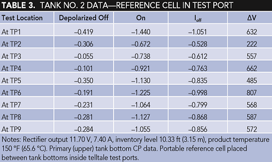
• Existing double bottom tank 85 ft (25.91 m) in diameter (Tables 2 and 3).
— Gas/oil tank operating at temperatures up to 160 °F (71 °C)
— A new double bottom tank installed five years earlier
— Double bottom installed without a nonconductive RPB v
— No CP to the upper tank bottom or lower tank bottom
— API 653 internal inspection after five years revealed soil side corrosion to the upper tank bottom due to galvanic effects of new tank bottom/old tank bottom, no CP, elevated temperatures, no nonconductive RPB
— Next API 653 internal inspection interval would be reduced for lack of sufficient CP and corrosion rate
— Tank bottom patch plates added primarily to the perimeter of the tank
— The old tank bottom and portion of old dead shell electrically isolated using structural fiberglass spacer installed and secured midway in the dead shell (Figure 3)
— A new perimeter angle drilled distributed CP system installed

Results of electrically isolating the upper tank bottom from the lower tank bottom and portion of the dead shell for Tank No. 2 are as follows:
• CP in accordance with NACE SP0193-2016 criteria at elevated temperature
• New perimeter CP system providing adequate CP current to the upper tank bottom
• Inspection interval extended to 10 years from five years
— $120,000 cleaning and inspection expenditure extended by five years
• Replacement tank bottom not required
— $340,000 expenditure eliminated
Conclusions
Utilization of this new and innovative method of electrically isolating the upper tank bottom from the old tank bottom and portion of the dead shell from outside the tank has been shown to allow for effective CP in accordance with NACE SP0193-2016 criterion of the upper tank bottoms. The concern about depleted CP systems between the tank bottoms has been eliminated, as CP current can now flow through the old tank bottom to the new (upper) tank bottom indefinitely. Significant cost savings to the owners have been achieved by eliminating the cost of cutting into the tank to cut away and/or remove the old tank floor, the cost of installing a new upper tank bottom, and the cost savings in extending the inspection intervals per API 653 of the tank bottoms by five years for adding effective CP in accordance with API RP 651.
This article is based on CORROSION 2019 paper no. 12924, presented in Nashville, Tennessee, USA.
References
1. Barletta, et. al., “Cathodic Protection of Aboveground Storage Tanks in An Arctic Environment,” CORROSION/95, paper no. 352 (Houston, TX: NACE International, 1995).
2. NACE SP0193-2016, "Application of Cathodic Protection to Control External Corrosion of Carbon Steel On-Grade Storage Tank Bottoms” (Houston, TX: NACE, 2016).
3. API RP 651, “Cathodic Protection of Aboveground Petroleum Storage Tanks,” fourth ed. (Washington, DC: API, 2014).