Reinforced concrete structures have been in use for many years in different applications. These structures can take a variety of shapes and sizes and can be designed to support many types of load conditions. In most cases, these structures can perform well for decades with relatively little or no maintenance. In industrial facilities, however, these structures are subject to a variety of adverse conditions. Exposure to the elements, thermal changes, and acid attacks are not uncommon. The structures in these facilities must accommodate all of these various exposures.
Reinforced concrete tanks are used in many gas plants to contain liquid sulfur. These tanks are usually buried, allowing only the roof and a small portion of the walls to be exposed. The size and structural framing of these tanks can vary.
The sulfur temperatures can range between 120 and 200 °C, resulting in significant thermal stress in the structure. The tanks are drained and filled daily, causing a cyclical change in load and temperature. Also, the sulfur vapor can combine with moisture to create a sulfuric acid (H₂SO₄) or a sulfurous acid (H₂SO₃). This combination of high acidity and high temperature results in an extremely aggressive and corrosive environment. Coatings are typically not used inside the tank, as they cannot withstand the combined effects of high temperature, acid attack, and erosion while still maintaining flexibility to bridge small cracks that can form in the concrete. Subsequently, the concrete is subject to attack, which can lead to deterioration of the structure.
The following case study presents the results of an evaluation and repair of a sulfur tank located at a gas plant in central Alberta by Read Jones Christoffersen Ltd.’s (RJC) (Edmonton, Alberta, Canada). The tank was constructed in 1978 and remained in service until 2009. In 1993, RJC began monitoring the condition of the structure, and repairs also started in 1993. Although the tank has been decommissioned in support of newer technologies, the repairs performed very well after 16 years of service and did not require any significant concrete repair since the initial program was completed, which exceeded the owner’s expectations for performance.
Structure Evaluation Tests
To assess the condition of the tank, a detailed evaluation was performed. The evaluation sought to determine the tank’s structural condition and the need for repair or maintenance, and to provide an indication as to the safety and expected remaining service life of the structure. The testing consisted of:
• A visual inspection of the exposed exterior elements to determine if there were any obvious signs of distress, deflection, or deterioration in the structure.
• An inspection of the interior of the tank to determine the condition of the structure. RJC says that while some tanks appeared to be in very good condition on the outside, it found that many were still suffering extreme structural distress on the inside. This was particularly evident on the underside of the roof structure and the interior surfaces of the upper portion of the walls, where exposure to acid attacks was greatest.
• Chain drag testing of the roof surface and hammer sounding of the vertical and soffit areas on the interior to locate where concrete delamination had occurred.
• An examination of the condition of the underlying reinforcing steel, which was helped with selective concrete removal.
• Materials testing to determine concrete compressive strength, air entrainment, cement type, and the depth of sulfur penetration in the concrete.
• A drawing review to obtain pertinent information on the structure, such as specified concrete cover, reinforcing details, cement type, and design criteria, so the most critical areas of reinforcement and how the structure was intended to perform could be determined.
• Finally, a design review to determine whether the existing level of deterioration had reduced the load-carrying capacity to where safety was compromised. Additionally, the design review could help to establish possible causes for any observed excessive deflection or cracking.
Structure’s Description and History
The sulfur tank in this study was constructed in 1978 and is 50-m long, 19-m wide, and 4.6-m deep. The lower 3.6 m of the tank is buried, with only the roof and 1 m of wall structure exposed. The structure is supported on a large 450-mm thick concrete pad, which acts as the floor slab and foundation. The roof is a 300-mm flat slab with 150-mm drop panels supported on 450-mm foundation walls and two interior rows of concrete columns, spaced by ~6,500-mm centers. In 1982, an explosion in the tank led to the replacement of the roof and upper portion of the walls.

Concrete deterioration was evident during a 1988 internal inspection. A sprayed concrete (shotcrete) was applied by the owners at that time to repair these areas. The next internal inspection was performed in 1990, and it was noted then that those repairs had failed. Shotcrete repairs were again performed under the direction of the owners in 1990.
In the spring of 1993, RJC performed an evaluation of the tank. At that time, the exterior structure displayed some cracking. However, it generally appeared to be in good condition. Chain drag testing of the roof did not reveal any significant deterioration.
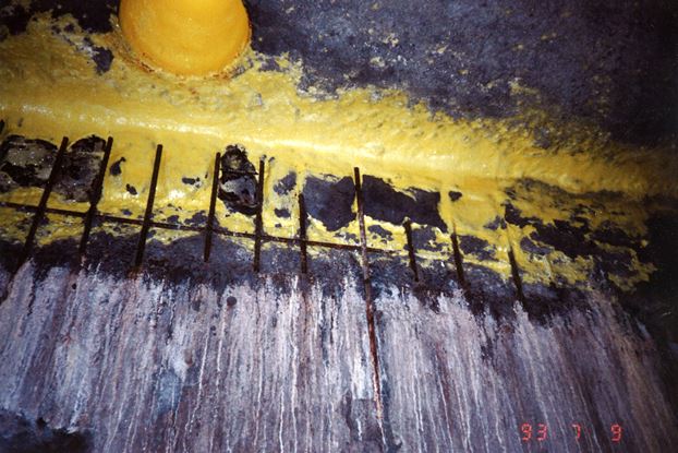
An internal inspection of the tank, however, uncovered considerable corrosion and concrete spalling of the upper portions of the wall, as well as areas on the underside of the roof slab (Figure 1). This corresponded with the region within the vapor space, where sulfur vapors and moisture had combined to form a highly acidic environment. Approximately 10% of the roof slab and 40% of the wall surfaces showed signs of deterioration. The shotcrete repairs performed in 1990 had totally failed, while the condition of the exposed reinforcing bars was varied. In some areas, the reinforcing bars were corroded through the entire cross section. Meanwhile, in other areas, the exposed reinforcing bars were in excellent condition, with no loss of cross section.
Selective removal of the concrete around the protected reinforcing bars determined that the concrete cover varied from 20 to 40 mm and that the bars were typically in good condition.
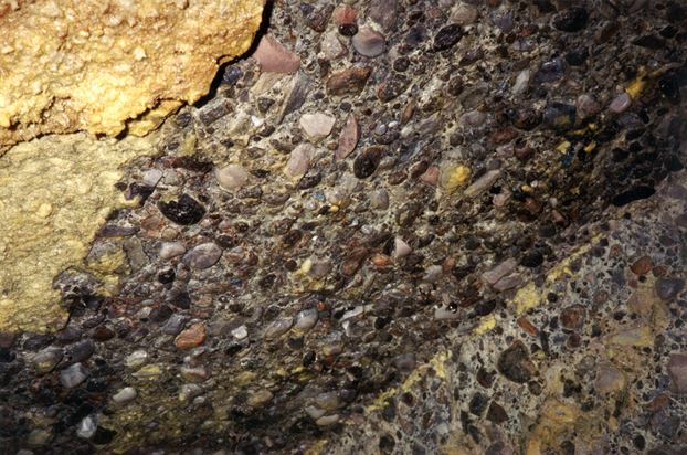
There was also a loss of cement paste and exposed aggregate in the underside of the roof and portions of the wall (Figure 2). This was relatively uniform, and RJC says it did not observe any exposed reinforcing steel in those areas.
Based on the deterioration evident, it was apparent that portions of the structure were unsafe, particularly at the roof slab—where there was concern for its ability to support the significant piping and equipment situated on the tank. It was necessary to develop a repair program that could perform the following tasks:

• Restore the load-carrying capacity of the structure to a safe condition.
• Perform in a very aggressive environment for a minimum specified period of time.
• Meet the owner’s budget requirements and time constraints.
Repair Methods and Materials
The level of deterioration evident in reinforced concrete structures can be greatly affected by the quality of concrete used during construction. Highly durable concrete, although not immune to damage, has generally been found to perform better and last longer than structures where the concrete was highly permeable or of poor quality.1 Poor workmanship, such as improper consolidation or insufficient concrete cover, can also result in premature deterioration.
In this project, the repairs previously completed for the owners had failed after a short time. These repairs consisted of a spray-applied concrete and vertical patch materials placed over the damaged areas. In some cases, mechanical fasteners and welded wire mesh were placed on the patch to anchor repair materials to the base concrete. These areas failed due to:
• Inadequate surface preparation, resulting in debonding of the repair materials.
• Improper consolidation and/or poor workmanship.
• Improper selection of repair materials and procedures.
• Corrosion of the reinforced steel beneath the repair materials.
• A lack of understanding regarding the behavior of the structure under applied loads and thermal stress.
The 1993 repair program consisted of partial and total replacement of the concrete members where structural damage was noted. Areas of exposed aggregate were not repaired during this program, as the deterioration evident had not affected the load-carrying capacity of the structure.
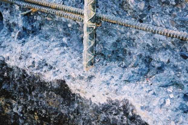
In the partial repair areas, concrete was removed beyond the inner layer of reinforcing steel and to a sound concrete substrate (Figure 3). The existing exposed steel was replaced with new steel where possible. The remaining reinforcing steel was sandblasted clean of any cement and corrosion product. The exposed concrete surfaces in the repair area were then thoroughly cleaned of loose materials and contaminants, thereby providing a suitable surface for bonding with the new repair materials.

Consideration was given to using high-alumina cement as a repair material. High-alumina cement has been used in the construction of similar tanks—although this material can be costly, relative to a regular Portland cement mixture. During the planning stages of the repair program, a cost-benefit analysis was performed based on the owner’s requirement for an expected 15- to 20-year life for the structure. On that basis, it was decided to repair the structure using a highly durable, low-permeability concrete.2 The concrete mixture design had the following properties:
• Type 50 sulfate-resistant cement.
• Low water/cement ratio of 0.40 (maximum) in American Concrete Institute (ACI) code.
• 8% silica fume.
• Air entrainment.
• 20 mm maximum aggregate size.
• Low slump (50 mm maximum).
• A minimum 28-day compressive strength of 35 MPa.
To increase protection to the reinforcing steel, a minimum concrete cover of 75 mm was provided in the repair areas.
Lined formwork was used to provide a smooth interior surface and to improve the durability of the repairs. To maintain the smooth concrete surface, the objective was to prevent any exposed steel from occurring on the interior surface—where exposure to the liquid sulfur and vapors could be present.
Proper curing of the repair materials can improve the performance of concrete. But in this case, extended curing periods were not possible due to time constraints on the plant shutdown. As a result, curing periods varied from seven days for vertical repairs to 14 days for the areas of slab replacement.
The total repair cost in 1993 for the project was ~CAN$400,000.
Performance of Repairs

The repairs performed in 1993 were examined in 1996 and 2000 during plant shutdowns. After 16 years of service, the repairs have performed very well with the following observations:
• The original concrete showed signs of deterioration and a loss of cement paste. Exposed aggregate was noted in many areas. Meanwhile, portions of the existing drop panels had also spalled from the underside of the roof slab.
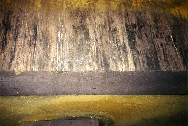
• In repair areas, the concrete surface was in excellent condition, with only localized areas where a minimal loss of surface paste was observed (Figure 4).
• Some fine cracks were noted in the repair areas. These appeared to be due to restrained shrinkage and thermal stress in the structure. On the whole, the repair areas were sound and performing as intended.
• Some loss of surface paste was noted in localized areas of the underside of the roof slab, adjacent to the steam injectors. It was determined that pressurized steam injected into the tank had deflected off the surface of the sulfur and abraded the concrete in the vicinity of the injectors. These injectors were installed after the 1993 repair program, and the damage was noted in 1996. The lines were relocated in 1996. During an inspection in 2000, there did not appear to be further deterioration in these areas.
• Approximately six small areas of debonded concrete (areas >0.1 m2) were detected in the repair areas in 1996. These were at the edges of repairs, and they may have been present due to shrinkage of the patches or from impact at the time the formwork was removed. There were no noticeable changes in these areas during the 2000 inspection.
Satisfied Owner
Strong performance of reinforced concrete structures exposed to aggressive environments can be achieved with the use of highly durable, low-permeability concretes and by paying careful attention to details. Consideration must be given to:
• The use of good quality concrete.
• Attention to construction details.
• Increased concrete cover.
• Design and detailing of the reinforcing steel to minimize cracking.
• Proper concrete curing.
RJC has applied these methods to a number of other sulfur tanks with similar results. This case study indicates that under extremely aggressive environments, proper use of concrete can result in a repair that is durable and economical. In this case, the repairs not only met, but exceeded the owner’s expectations for performance.
References
1 ACI 222R-89, “Corrosion of Metals in Concrete,” (Farmington Hills, MI: ACI, 1989), p. 30.
2 CAN/CSA-S413-94, “Parking Structures—Structures Design,” (Mississauga, Ontario, Canada: CSA, 1994), p. 103.