A Mexican retail chain purchased the old Selem Cinema from the city of San Francisco de Campeche, Mexico, to convert it into its largest department store in the country. The 70-year-old Selem Cinema opened on January 27, 1951, and is constructed of reinforced concrete (Figure 1).
Due to its antiquity and location inside the perimeter of buildings in the historic center of San Francisco de Campeche, named Cultural Heritage of Humanity in 1999, the National Institute of Fine Arts (INBA, in Spanish) and the National Institute of Anthropology and History (INAH, in Spanish) considered it as a building of historical value. For that reason, the property could not be demolished but restored. This presented a challenge to the owner company, since the initial executive project included complete demolition and entirely new construction.
 The building, which had been abandoned for more than 15 years, had evident damage from deterioration, caused mainly by carbonation of the concrete and corrosion of the reinforcing steel, as partially seen in a superimposed corrosion potential map on one of its columns (Figure 2). Rescuing the property depended on a strategy that included a detailed evaluation, diagnosis, and repair/rehabilitation that would allow more than 80% of the old structure to be rescued and combined with a new interior structure made of durable concrete. The durability of this property, once repaired and merged with the new part, was estimated to be 100 years, following a preventive maintenance plan. The objective of this article is to present the criteria followed for the evaluation, diagnosis, and repair of the columns, and to control cracking and apply a criterion to extend the service life of the restored structure by 100 years.
Possible Causes of Observed Damage
The structure functioned as a cinema for 40 years, then was abandoned, and later reopened as a parking garage, until it was completely abandoned in 2016. The carbon dioxide (CO2) from this microenvironment, together with small water leaks, created optimal conditions for carbonation, corrosion, cracking, and spalling of the concrete cover over large areas.
Due to its condition, with severe damage in low parts that decreased to insignificant damage at higher elevations, and its kinetics (low annual carbonation rates), the problem was classified as low intensity, but had progressed to advanced deterioration as of 2016. The results from initial work shown in Figure 3 would partially ascertain these hypotheses. This would give an opportunity to make calculations for repairs, interfacing with the new structure, and extending its service life.
Evaluation, Diagnosis, and Repair Strategy
 Being a structure of ~1,000 m2, a measurement of corrosion potentials (Ecorr)1 was made in the structural elements (beams and columns) after which specific elements were selected to make measurements of corrosion rate (icorr)2 and electrical resistivity (Rs).3 With these data, easy-to-understand diagrams were drawn up for the workers so that the intervention areas were located.
Diagnosis
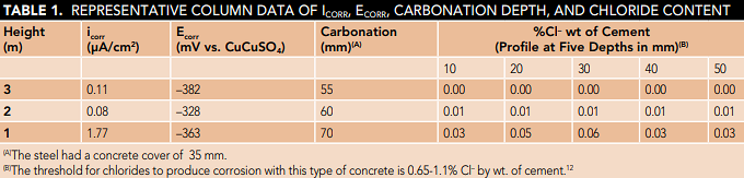
The distance to the sea (500 m), the maximum carbonation coefficient obtained4 (11.35 mm/y1/2), and the maximum amount of chlorides5 (0.06% Cl– by wt of cement) confirmed the atmosphere C3 of Campeche.6-8 In Table 1, the results of icorr, Ecorr, carbonation, and chlorides of a representative column indicate slow kinetics of damage from bottom to top. The kinetics were accelerated when the structure functioned as a parking garage when there were also some sources of moisture. Hence, at 3-m height, the damage was negligible in several areas. This coincides with the trend observed in carbonation.
According to the diagnosis, the repair was proposed according to mechanisms already known.9-11
Repair
Once evaluated, the areas were classified according to the type of repair to be carried out:9-11
a) Localized surface repair (maximum depth of 2 cm, before reinforcement)
b) Uniform surface repair (throughout the element)
c) Localized deep repair (depth greater than 2 cm or that crosses the outer reinforcement level)
d) Uniform deep repair
The case illustrated in Figure 3 corresponds to a uniform deep repair. In this case, it would be necessary to rely on tests to guarantee that the repair helped to control the appearance of future cracks and also that its design allowed an extension of the service life of up to 100 years. Figures equivalent to Figure 3 were constructed for each element, with specific recommendations to proceed with the repair and demolition (if required).
The structural assessment and the continuity of the structure between beams, slabs, and columns allowed an intervention following the repair strategy illustrated in Figure 3.9-11 This strategy consisted of demolishing sections of 1.5 m in height starting from the bottom of the column, and as far as required. Repair with the orthogonal replacement of concrete helped to redistribute column loads evenly over the horizontal plane of the new-old concrete joint, thereby ensuring that the mechanical strength of the new concrete is the same as old concrete and cracking was controlled.
Demolition and Restoration
Due to the severe damage observed and the INBA and INAH restrictions for restoration, a conventional demolition could not be undertaken as there was a risk that in doing so, parts that needed to be preserved would crack and detach.
Then, it was decided to repair the entire structure, and then demolish the elements required by the approved project, with the assurance that what had already been repaired would not be demolished. The repairs were carried out in sections of 1.5 m, starting from the lower parts upward. Repairing and then demolishing allowed embedding the anchors that would serve to blend the new building with the old building. This is common practice in this type of intervention, but in this case, we were talking about an old building with 26 MPa concrete and a new building with 25 MPa concrete. Part of this strategy is illustrated in Figure 4.
Service Life Extension
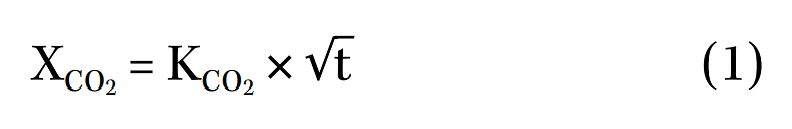
According to the previous information, the extension of the service life of the original part of the old Selem Cinema would be mainly a function of the carbonation of the concrete, which for its new extension of service life would be the possible and only main condition. The carbonation coefficients were then calculated. One of the simplest models that allow predicting the carbonation rate of concrete is the one that relates the carbonation depth with the square root of the exposure time, as expressed in Equation (1):

where XCO2 = carbonation depth, in millimeters, with an approximation to one-tenth;
KCO2 = carbonation constant in mm/y1/2, with an approximation to one-tenth; and t = exposure time of the concrete to the environment, in years.
According to the NMX-C-515-ONNCCE-20154 standard, concrete is considered good with high resistance to carbonation when it has a KCO2 < 3 mm/y1/2, an average quality when 3 mm/y1/2 < KCO2 ≤ 6 mm/y1/2, and is considered bad with low carbonation resistance when K CO2 > 6 mm/y1/2. Under these criteria, and based on the evaluation carried out, it was possible to verify a higher CO2 intake in the lower levels of the columns (Figure 5). This was mainly due to the change in use from being a cinema to serving as a parking garage where maintenance was scarce or null and CO2 emissions were concentrated, causing the maximum KCO2 to be 11.35 mm/y1/2.
The values in Figure 5 show the behavior of KCO2 of the columns evaluated with different concrete coatings, according to the micro-environment for the same exposure time. Those KCO2 values close to 4 mm/y1/2 generally corresponded to elements located in places far from the area that functioned as a parking lot, to places that started at 3 m in height, even where some elements had a coating of granite-like material on concrete. The granite was removed, and the carbonation was measured obtaining KCO2 = 3.59 mm/y1/2, so once again the service life with this KCO2 value was estimated. Therefore, the corrosion-level carbonation would reach the steel in 124 years.

Based on this experience with concrete covers and coatings (barriers) and that the service of the structure would be for commercial use, it was recommended to use a primary oxide-converting and anticorrosive coating applied to the reinforcing steel and the application of a crystalline coating on the finished concrete. This helped to create a barrier against the penetration of aggressive agents. Further, to verify the state of the structure, and that the projection was being fulfilled, a preventive maintenance plan was made.
Conclusions
A reinforced concrete building almost 70 years old with historical value was evaluated and diagnosed with durability criteria. Based on the results, the repair was designed with a prediction of 100 years of service life extension. This was achieved considering a steel coating and a concrete coating (barrier effect) that produced a similar or better protective effect than that recorded during the evaluation. A preventive maintenance plan was designed to help achieve the service life extension.
Acknowledgments
The authors appreciate the support of Coppel SA de CV, UACAM, Cinvestav, INAH, and INBA, as well as M. Josefa de los Ángeles for her technical support and J.A. Briceño-Mena, thanks to his Conacyt Ph.D. grant.
References and About the Authors