Severe external corrosion was found on the casing of the SS-25 gas well that broke open at the Aliso Canyon gas storage facility near Los Angeles, California, USA, in October 2015 and caused an estimated release of 4.62 billion ft3 (130.8 million m3) of gas,1 according to independent investigators hired to determine the leak’s cause.
The failure, which occurred near the Porter Ranch neighborhood of Los Angeles, took place in one of the 114 gas wells operated by Southern California Gas Co. (Los Angeles, California, USA) at the Aliso Canyon facility. It took until February 2016 for it to be completely sealed.
In the aftermath, engineering consultancy Blade Energy Partners (Frisco, Texas, USA) was granted authority by the California Public Utilities Commission (CPUC) (San Francisco, California, USA) to conduct a root cause analysis of the metallurgical and fractographic aspects of the gas leak. The initial findings were sent to CPUC on February 15, 2018, and CPUC then published the report on its government web site.2
The report contains the first publicly available photos of the blown-out well casings. One of the most immediate findings was a casing at the failure site that had extensive corrosion on the outside where it ruptured.
Methodology of the Probe
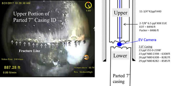
To analyze the rupture, investigators first inspected the area with a downhole video camera on August 30, 2017, which identified a fully parted 7-in (178-mm) casing located ~892 ft (272 m) beneath the surface.

From there, investigators extracted 24 total casing joints from the well for comparison purposes—including the joint associated with the parted casing. Both the top and bottom fracture surfaces of the parted casing were recovered.
The casing, casing connections, tubing, and wellhead equipment were transported from the Aliso Canyon site to Blade’s storage location in Texas for further evaluation. According to the company, the items were transported under strict security protocols with appropriate corrosion protection in place. This was done to maintain the chain of custody process.
Evaluations taking place include surface mapping, fractographic examinations, mechanical testing, and three-dimensional (3-D) reconstructions, according to the latest report, which outlines various protocols to be used in their analysis. Testing is taking place at the Element Materials Technology laboratory in Houston, Texas, USA.
Parted Casing Findings
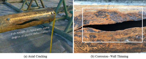
A final report has yet to be issued. In the interim, the most recent report presents findings from the on-site examination by investigators. With regards to the parted casing, visual examination in the field showed both a circumferential fracture and a 19-in (483-mm) long axial crack on the lower part of the casing, which had merged with the fracture.

The crack bulged with some degree of plastic deformation, the investigators say, adding that severe external corrosion was observed in the failure areas. This indicated that the axial split was associated with wall thinning due to corrosion, according to the report.
As part of future testing steps on the casing, specifically at the failure site, investigators plan to fully reconstruct the fracture from both the upper and lower parts of the casing to ensure there are no missing fracture fragments.
Trends from Other Joints
The field investigation also revealed several trends when comparing joints from different sections of the well. Namely, the severity of corrosion generally increased with greater depth, with the most severe corrosion seen at the failure site in Joint 22.

By comparison, Joint 2 at a depth of ~20 to 60 ft (6 to 18 m) showed little corrosion, Joint 14 at a depth of ~518 to 560 ft (158 to 171 m) showed shallow corrosion, and Joint 20 at a depth of ~770 to 811 ft (235 to 247 m) revealed a large area of deep corrosion.
Another type of indication found during the field examination had oblique, shallow crack-like features, with the angle of the crack-like features slightly deviated from the longitudinal axis of the casing. The features were identified by visual examination and then confirmed by field magnetic particle and ultrasonic inspection, according to the investigators.

The indications could be seen on the casing surface both before and after applying white contrast paint. Areas of mechanical damages such as gouges, tong marks, slip marks, and possible erosion/corrosion marks were also observed.
Laboratory testing to confirm the field observations will be included in the final report. Many of these tests are still ongoing; and a final report on the well failure, with full lab results, is expected by November 2018.
Source: California Public Utilities Commission, www.cpuc.ca.gov; Blade Energy Partners, www.blade-energy.com.
References
1 “PHMSA Issues Final Rule on Changes to Gas Pipeline Safety Regulations,” Materials Performance, January 11, 2017, http://www.materialsperformance.com/news/2017/january/phmsa-issues-final-rule-on-changes-to-gas-pipeline-safety-regulations (April 10, 2018).
2 “Aliso Canyon RCA Phase 4 Protocol for Metallurgical Investigation of the SS-25 Failure,” Blade Energy Partners, Project Number SCG-16-001, February 15, 2018, http://www.cpuc.ca.gov/uploadedFiles/CPUC_Public_Website/Content/Safety/Natural_Gas_Pipeline/Blade%20RCA%20SS-25%20Metallurgical%20Protocol%20-Phase%204%20RCA.pdf (April 10, 2018).