Collecting adequate data when performing alternating current (AC) interference studies is imperative. Accurate information can prevent expensive installations and eliminate the incorrect positioning of AC mitigation systems.
Certain features, such as drains via direct or indirect bonds with other structures, actual pipeline coating resistance vs. theoretical values, existing AC grounding, and anomalies like extraneous earths, can all affect the overall accuracy of the computational model for the AC interference.
Computer modeling of the AC interference effects on buried pipelines has been in use for some time, and the input data creates various results and outputs. With recent improvements, it has become an engineering best practice for the pipeline industry, most notably with complex pipeline and high-voltage AC (HVAC) right-of-ways. However, variances in input data and measurements can lead to considerable variances and possible integrity issues.
Different Features
It is important to remember that different features may have a substantial impact on the pipelines’ coating resistance. One such consideration is the soil resistivity near the pipeline route, which can affect the computed AC voltages and current densities (CDs), leading to concerns regarding safety and corrosion of the pipeline.
The modeling results depend heavily on the spacing of the soil resistivity measurements, which influence the mitigation design and integrity. Clearly, measurements taken at 1,000 ft (304.8 m) vs. 5,280 ft (1609.3 m) would yield differing results. The measurements themselves do not affect the corrosion threat, but could affect the accuracy of the modeling, the understanding of the interference, and how an owner/operator responds to the threat.
No standards exist that require computational calibration, which would ensure the modeling replicates actual field conditions in the specific AC collocation, while considering the entire pipeline infrastructure. However, accurate collection of field data can significantly improve the precision of the computational modeling. Such measurements include: AC pipe-to-soil potential (AC PSP); longitudinal electric field (LEF); electro-magnetic force (EMF); current drains at any cross bonds; AC current drains and AC PSP measurements at existing AC mitigation locations; and soil resistivity measurements.
The interference collocation can then be calibrated for the as-is situation. When this information is used for the remainder of the computational modeling, it assures greater overall accuracy.
 Additionally, no standard exists outlining the way in which resistivity measurements should be collected, nor a minimum required interval for the AC interference study. It is important to note that although the soil resistivity measurements might not influence the coating resistance of well-coated pipelines, the required CD calculations with respect to the AC corrosion risks rely heavily on the prevailing soil resistivity at pipe burial depth. Because software outputs are only as good as the accuracy of the inputs, certain models might not produce the accuracy needed.
Case Study Details
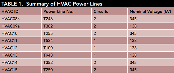
Researchers Gerald J. Haynes and Christophe Baeté with Elsyca, Inc., along with Tyson Manning and Lance Barton with Structural Integrity Associates, Inc. in their paper, “Variances in Pipeline AC Interference Computational Modeling,” validate the importance of accurate soil resistivity data along the AC interference collocation.1 For their computational model, they studied a 1-in (2.54-cm) pipeline, with a 0.25-in (0.64-cm) wall thickness, buried at a depth of 4 ft (1.22 m). This pipeline collocates with eight HVAC powerlines. Figure 1 shows the HVAC powerlines and Figure 2 shows a Google Earth overview.
 The section of the pipeline used for the study also has existing AC mitigation systems with nine locations. They include four mitigation ribbons, two grounding mats, and three grounding cells. The AC PSP measurements and AC grounding current measurement for each of the AC mitigation sites were supplied to the researchers.
Also, there are two existing valves and one existing CP rectifier. A liquid external coating with an overwrapped tape system was used with a uniform coating resistance along the entire length. The HVAC powerline information in Table 1 was known, but not the average/operating load information, so the current loads were computed using the measured EMF, LEF, and AC PSP as part of the calibration process.
The soil resistivity data were collected, and values were measured at 2.5-ft (0.76-m), 5.0-ft (1.52-m), 7.5-ft (2.29-m), and 10-ft (3.05-m) intervals. The soil resistivity measurements were collected nominally every 0.12 mi (0.19 km). In an effort to emphasize the different results attainable, the researchers performed modeling using soil resistivity measurements at three locations, six locations, every 1 mi (1.6 km), and nominally every 0.12 mi along the AC interference collocation and/or affected route.
Results and Conclusions
The research team was able to achieve a good correlation between the computed and measured data (Figure 3). A slight mismatch exists between the computed and measured data, which is to be expected due to slight load fluctuations and the cable routing not being exactly parallel to the conductors. The soil resistivity along the route was found to be highly influential on the AC corrosion CDs, affecting the overall integrity risk to the pipeline.
The study results reveal that the accuracy of the computational modeling can be increased by utilizing accurate LEF, EMF, and AC PSP site measurements. Furthermore, the actual pipeline conditions may not be correctly known without calibrating the computational model.

An objective of the study was to prove that the soil resistivity data collection process must be properly described, and the collection intervals specified. Overestimating or missing the AC corrosion risks altogether can cause costly and unwarranted mitigation and serious long-term consequences. Because of this, the researchers recommend updates to specifications that fully describe the input requirements for site measurements required to accurately compute the AC corrosion risks, plus the minimum requirements for computational modeling of AC interference.
Without any specifications, codes, standards, or guidelines about the computational modeling of AC interference and AC corrosion, they note, contractors have the ability to perform the computational modeling at will. Low bids might win a project, but have devastating results.
Reference
1 G.J. Haynes, et al., “Variances in Pipeline AC Interference Computational Modeling,” CORROSION 2019, paper no. 12985 (Houston, TX: NACE International, 2019).