For many decades the maritime industry has depended on icebreaker ships to forge a path through ice-covered waters so other ships can safety navigate the trade routes in the polar regions of the world. Scientific studies carried out in the Arctic and Antarctic also have relied on icebreakers for support. More recently, ice-breaking vessels are being used to assist offshore drilling in the Arctic seas by supplying equipment and supplies to drilling sites as well as managing nearby ice floes and icebergs. Several characteristics differentiate ice-breaking ships from other ships: a strengthened hull, an ice-clearing shape that is specifically designed to direct broken ice around or under the vessel, and the power to push through sea ice.1
 Ice along the Northern Sea Route in the Arctic Circle varies from 4 to 6.5 ft (1.2 to 1.8 m) during the winter, and in central parts of the Arctic Ocean, the ice averages 8 ft (2.4 m) thick.2 The effects of breaking ice can be extremely destructive to the steel hull of an ice-breaking vessel. Ice abrasion can damage the external hull’s protective coating, which leads to exposure of bare steel and rapid corrosion. To protect the hulls of these ships from corrosion, a combination of protective coatings and impressed current cathodic protection (ICCP) is often used.
According to researchers Min-Jeong Lee, senior engineer, and Chae-Seon Lim, principal research engineer, both in the Material & Coating Research Department at Samsung Heavy Industries, Co., Ltd. (Geoje, Gyeongsangnam-do, South Korea), the performance of a CP system for a ship’s external hull is dependent on several factors, including the geometry of the ship’s hull, the resistivity of the surrounding seawater, the chemicals in the seawater, and the degree of coating damage. The ICCP design for many commercial vessels is often based on current density (CD) calculations and the designers’ experience rather than an analytical method. For an icebreaker travelling in Arctic conditions, the researchers note, this traditional approach to CP design may not result in an adequate amount of corrosion protection for the hull in this environment. There are several challenges to consider, says Lee. One challenge is the resistivity of the Arctic seawater. Seawater resistivity is a function of salinity and temperature. Because of its lower salinity and cooler temperature, Arctic seawater has a higher resistivity than seawater in tropical or moderate climates, which, in turn, reduces the conductivity of the Arctic water and decreases the coverage of the CP current. Another challenge is the amount of CP current required for adequate protection, which is increased due to the high oxygen content of the Arctic seawater as well as its resistivity. Additionally, the hull coating damage experienced by an icebreaker is very different than the typical coating damage a ship would sustain in non-icy waters.
 To determine the optimum ICCP design for the external hull of an icebreaker, the researchers explored a modeling approach using computational analysis based on the boundary element method (BEM). Lee comments that modeling tools are often used to design ICCP for stationary offshore structures such as oil and gas production platforms, floating production, storage, and offloading (FPSO) units, and semi-submersible reefs; but they are not typically used to model CP for ship’s hulls, especially the hull of an icebreaker. Basically, these tools are computer software packages that use data input about the conditions of the steel structure to be protected, such as polarization data, seawater resistivity, and coating breakdown, and information about the CP design, including the type, number, and location of the anodes and the CD, to calculate the effectiveness of the CP design for that particular structure. The tools create a virtual, three-dimensional model of the structure that uses color to illustrate the areas that are adequately protected by CP and areas that are not well protected and need additional CP coverage. The researchers used commercial modeling software (BEASY Corrosion & CP† and BEASY ICCP Optimisation†) to better understand the differences in CP design requirements for the external hull of an ice-breaking ship vs. a typical commercial ship that usually travels in more temperate waters, and to determine if such a modeling tool, when compared to actual measurements, is a reliable technology for designing a CP system for a ship’s hull.
Criteria for Modeling a Typical Commercial Vessel
As part of their study, the researchers modeled a typical ICCP design for the external hull of a commercial vessel with a hull length of 200 to 300 m (e.g., container ships, tankers, and liquefied natural gas [LNG] carriers) in temperate climate conditions. This ICCP design consisted of four mixed-metal oxide-coated titanium (MMO-Ti) anodes—two anodes at the bow and two at the stern—and four reference electrodes located at least 8 m from the anodes.
 The researchers applied the typical resistivity for open seawater with a temperature <10 °C, which is 30 O·cm. Using information based on a paint manufacturer’s observations of coating damage during the dry docking of commercial vessels, the researchers assumed the maximum percentage of coating degradation at the end of the coating’s design life ranged between 1 to 5%, depending on the region of the external hull. The coating breakdown they used was 5% at the bow, 3% on the sides, and 1% on the bottom.
The CD needed to maintain the correct corrosion protection potential will vary according to operating conditions and is affected by the condition of the coating. For traditional ICCP system designs, the researchers comment that a constant CD is normally applied to the entire hull, and typically a mean CD of 35 mA/m2 is used regardless of the coating condition. For this model, the researchers used a bare steel CD of 200 mA/m2 based on guidelines published by Germanischer Lloyd 3 for temperate climate conditions, and multiplied it by the coating breakdown percentages (i.e., 1 to 5% [0.01 to 0.05]) to determine the required CD for the various regions of the external hull, which were 2 mA/m2 for the bottom, 6 mA/m2 for the sides, and 10 mA/m2 for the bow.
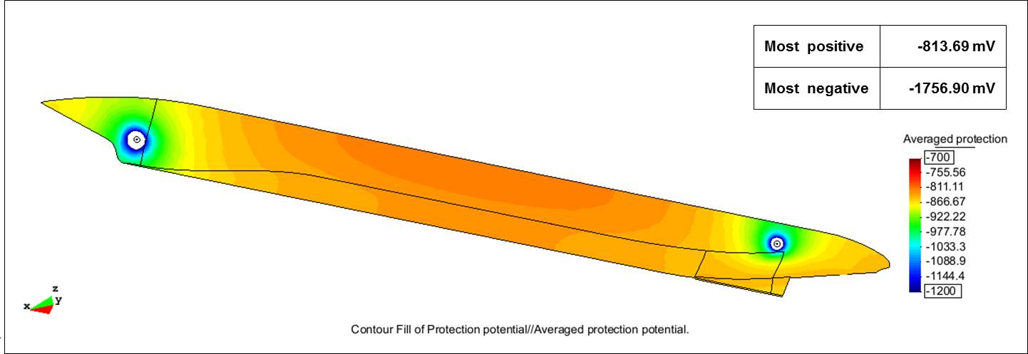
A steel potential of -850 mV vs. a silver/silver chloride reference electrode in seawater (Ag/AgCl/seawater) was chosen as the desired protection potential, and a potential of -2,000 mV vs. Ag/AgCl/seawater was selected as the maximum overprotection potential to safeguard coating integrity adjacent to the anodes. According to the researchers, most marine protective coatings can resist CP disbondment down to this negative potential value. The model, when executed, displayed the potential distribution for this ICCP design and showed the potentials were within the targeted range and the entire external hull was protected against corrosion. The most positive potential was -813.69 mV and the most negative potential was -1,756.90 mV.
Criteria for Modeling an Ice-Breaking Vessel
For comparison, the researchers modeled the same typical ICCP design for an external hull of a double-acting tanker (a type of ice-breaking cargo ship designed to run forward in open water and thin ice, and turn around and proceed astern in heavy ice conditions4) that travels across the Barents Sea in the Arctic. The ICCP design used for the modelingresearch, four MMO-Ti anodes—one pair at the bow and one pair at the stern—and four reference electrodes, is very similar to the tanker’s actual ICCP design, says Lee.
The ship has a submerged hull area of 12,675 m2 that is coated with a 500-µm thick layer of a solvent-free epoxy with low ice adhesion and good friction resistance, a formulation designed specifically to withstand ice impact and abrasions to ice-going vessels. About every two to five years, the vessel is put into dry dock for external hull coating maintenance. Using information on the end-of-service-life coating condition of other ice-class vessels traveling along the same Arctic sea route as the double-acting tanker and protected with the same applied coating system, the researchers assumed a coating breakdown of 5% for the bow and stern areas of the external hull where the ice load is heaviest. Coating breakdown for other regions of the external hull were assumed proportionally from an ice load value and varied from 1% for the flat bottom of the hull and 3% for the sides of the hull to 4% for the regions adjacent to the bow and stern.

The resistivity of the Arctic seawater was defined by the researchers as 60 O·cm, derived from a salinity of 1.9% and a temperature of 0 °C, which they consider to be representative of the most severe conditions that can be encountered on an Arctic voyage.
A steel potential of -800 mV vs. Ag/AgCl/seawater was chosen as the ideal protection potential, and the maximum overprotection potential selected was -2,000 mV vs. Ag/AgCl/seawater. For this model, the researchers used a bare steel CD of 250 mA/m2 for Arctic conditions, per DNV-RP-B401,5 and multiplied it by the coating breakdown percentages to determine the required CD for the various regions of the external hull, which were 2.5 mA/m2 for the bottom; 5.0 and 7.5 mA/m2 for the lower and upper sides, respectively; 10 mA/m2 for areas bordering the bow and stern; and 12.5 mA/m2 for the bow and stern.
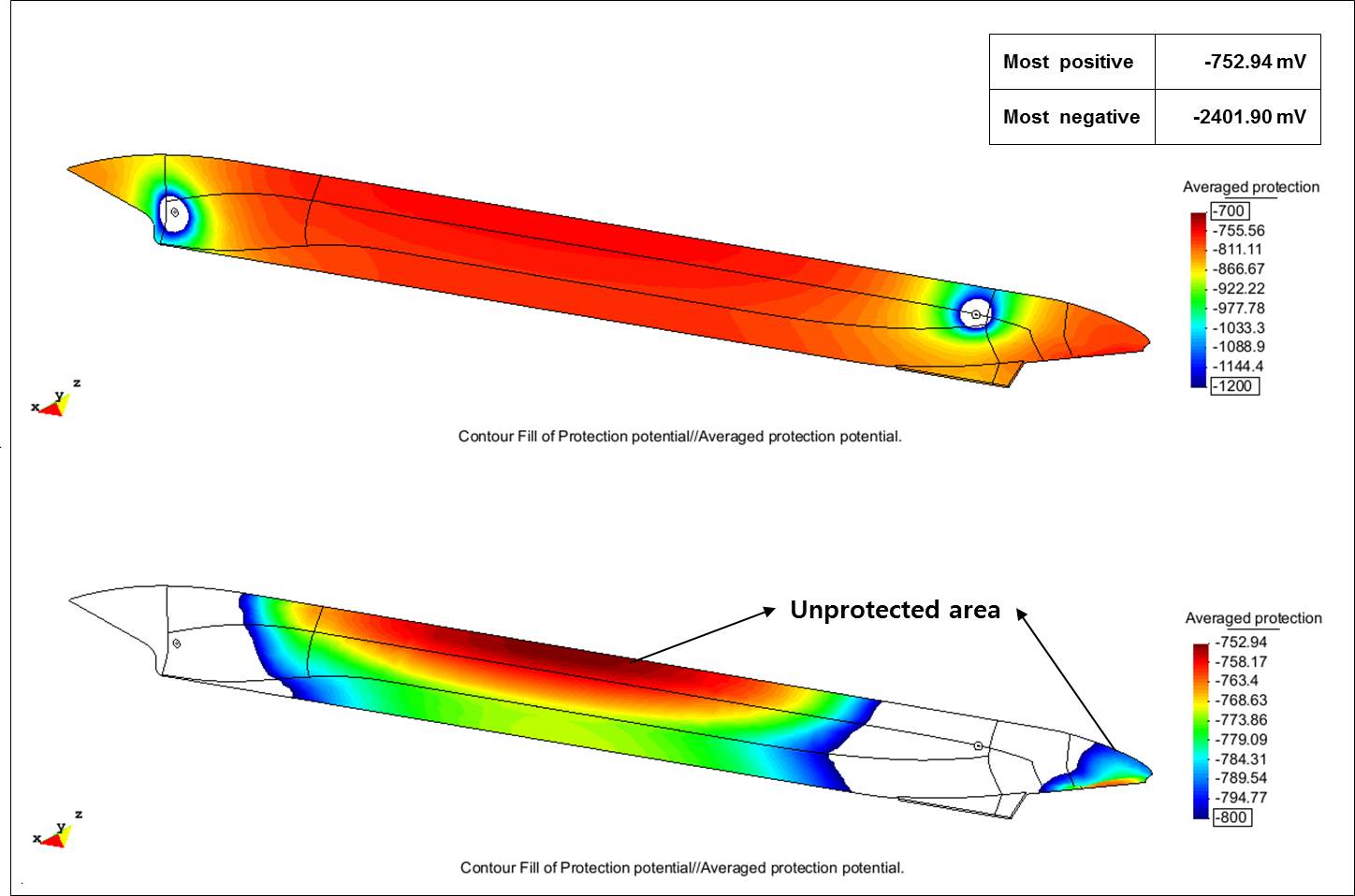
When run, the model showed that the typical ICCP design would not provide adequate corrosion protection for the hull in Arctic conditions, and leave large areas of the hull, particularly the sides and bottom, polarized with potentials less negative than -800 mV while overprotecting areas adjacent to the anodes. The most positive potentials were -752.94 mV and the most negative were -2,401.90 mV. “For this ship, the model determined that the ICCP design is not optimized,” Lee observes, noting that the current from the four anodes was not enough to cover the entire hull.
Optimizing the ICCP System
The researchers explain that modeling can be used to optimize the ICCP system design by virtually rearranging the location of the anodes and reference electrodes on the external hull. The computer model can predict the resulting potentials of each design until uniform distribution of potentials on the hull is achieved, which ensures the protection potentials are within the specified range on the entire hull and under- and overprotection are avoided. This is helpful, they note, when the arrangement of anodes and reference electrodes must be restricted for various reasons, such as longitudinal arrangement of protuberances, risk of mechanic damage of anodes during voyages and/or at the pier, cabling installation limits in hazardous areas, etc.
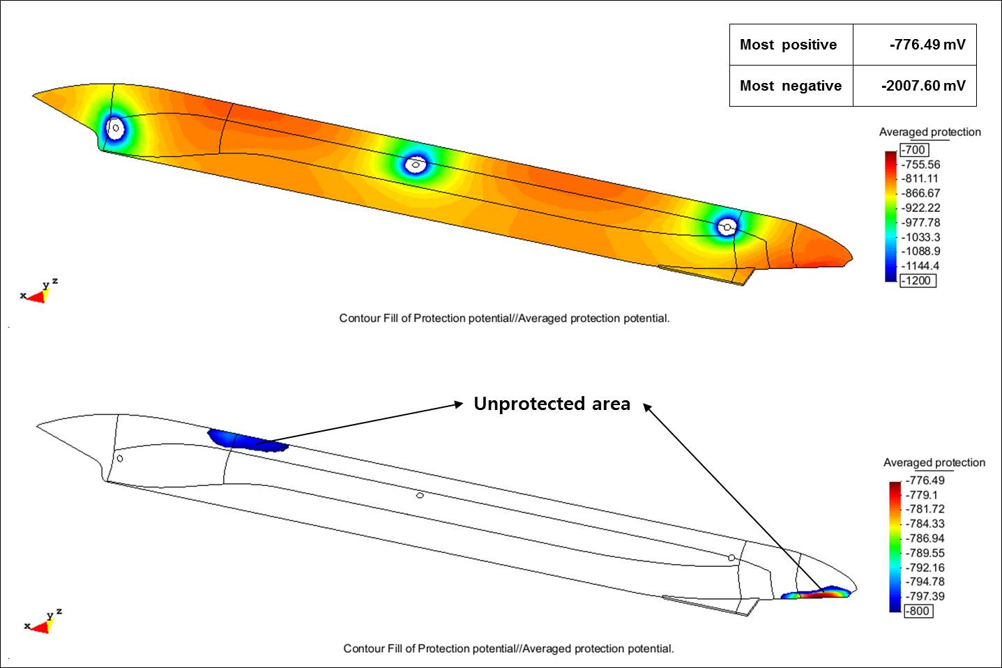
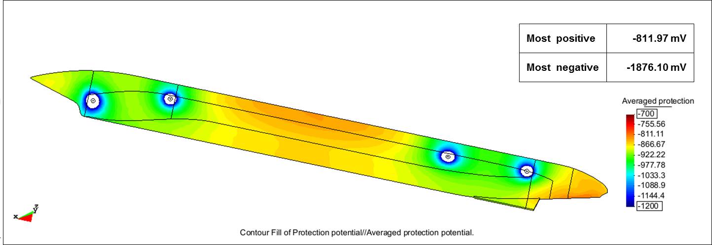
Because the typical ICCP design was not optimum for the double-acting tanker in Arctic conditions, the researchers modeled a second ICCP design. They added an anode pair in the middle of the external hull where the potential was most positive in the previous design. Although protection from CP improved, portions of the hull were still unprotected. The most positive potential was -776.49 mV and the most negative was -2,007.60 mV. So another design was developed and modeled by the researchers that used a total of four pairs of anodes—two pairs near the bow and two pairs near the stern. This configuration achieved full protection of the hull, with values of -811.97 mV for the most positive potential and -1,876.10 mV for the most negative potential. Both values fell within the range set by the researchers—between -800 mV and -2,000 mV.
The researchers concluded that designing an ICCP system to provide optimum protection is complex, and precise placement of anodes and reference cells is important for vessels with varying degrees of coating degradation on the external hull. Using computational analysis and modeling was successful in determining that an ICCP system design is effective for a vessel exposed to Arctic seawater conditions. Going forward, Lee expects more use of CP modeling when designing ICCP systems for ship hulls, particularly those headed for the Arctic.
More information on the modeling study can be found in CORROSION 2014 paper no. 4004, “ICCP System Design on the Hull of an Ice Breaker by Computational Analysis,” by M.-J. Lee and C.-S. Lim.
†Trade name.
References
- “Icebreaker,” Wikipedia, the free encyclopedia, http://en.wikipedia.org/wiki/Icebreaker (February 10, 2015).
- “Nuclear-Powered Icebreaker,” Wikipedia, the free encyclopedia, http://en.wikipedia.org/wiki/Nuclear-powered_icebreaker (February 10, 2015).
- “Rules for Classification and Construction” (Hamburg, Germany: Germanischer Lloyd, 2010).
- “Double Acting Ship,” Wikipedia, the free encyclopedia, http://en.wikipedia.org/wiki/Double_acting_ship (February 10, 2015).
- DNV-RP-B401, “Cathodic Protection Design” (Høvik, Norway: DNV, 2010).