Offshore wind power has gone from a marginal industry to a major renewable energy source in Northern Europe within the last decade. According to the latest offshore wind operational report prepared by The Crown Estate,1 the technology that barely existed 10 years ago in the United Kingdom has multiplied 10-fold, with over 30 wind farms supplying ~5.4% of the United Kingdom’s total estimated electricity consumption in 2016. At the end of December 2016 there were 29 offshore wind farms with a total of 1,463 fully operational offshore wind turbines on the U.K. seabed that generated over 5.1 GW of operational capacity. An additional 14 offshore wind farms with a total of 830 wind turbines are now under construction in the United Kingdom and expected to add new operational capacity of 5.3 GW.
Lynn and Inner Dowsing (LID) is a combination of two wind farms located off United Kingdom’s East Lincolnshire coastline in the North Sea. Project construction started in 2006 and the wind farms became operational in 2009. LID is comprised of 54 monopile foundation wind turbines with an output capacity of 3.6 MW each for a total maximum output of 194 MW. The monopiles and their steel transition pieces were installed in 2007 and the turbines in 2008.2
The monopile foundation is currently the most common type used on wind turbines due to its ease of installation in shallow to medium water depths (up to 30 m deep).3 A typical monopile foundation consists of a hollow, ~4- to 6-m diameter steel pile with ~50-mm thick walls that is driven ~25 m into the seabed. Usually 1 to 2 m of the pile structure is above the water line and a portion of the monopile’s interior remains flooded.
The transition piece, which supports steel components such as boat landings, ladders, and platforms required for accessing the wind turbine, is installed over the top of the monopile with an overlap of ~6 to 9 m. The annular space between the monopile and the transition piece is then filled with high-strength grout that cements the two pipes together. While in service, the transition piece will settle slightly from vibration of the turbine or broken bonds between the steel and the grout. The bottom end of the transition piece (called the lower platform) is sealed, and sits inside the top of the monopile. For a large number of designs, internal J-tubes are used to house the turbine’s electrical connection cables. They enter the base of the monopile near the sea floor and run up the inside of the pile into the transition piece. Specially designed seals are used at the interface between the monopile wall and the J-tubes to create an airtight space within the monopile.
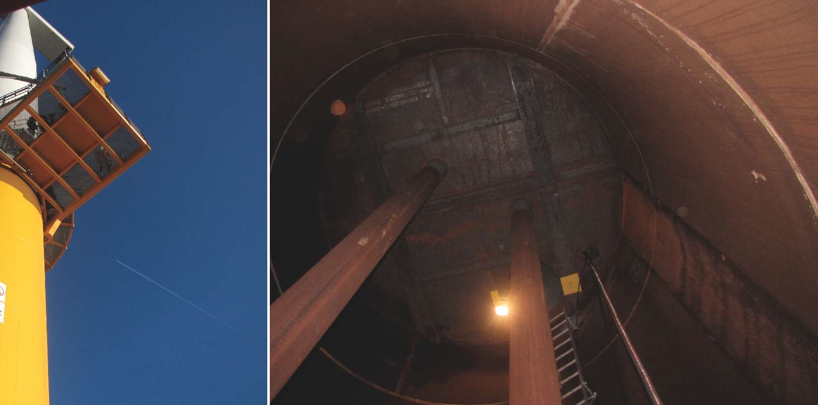
According to NACE International member Alex Delwiche with Deepwater EU, Ltd. (Surrey, United Kingdom) and Isaac Tavares with Centrica plc (Windsor, United Kingdom), the early version of a design standard for offshore wind turbines prepared by DNV4 noted that corrosion protection on the inside of the monopile is not required if the pile is airtight (i.e., there is no or very low oxygen content) and the structure is non-corroding. Construction of the LID structures followed this design standard, Delwiche notes, so cathodic protection (CP) or any type of coating was not applied inside the LID monopiles or the transition pieces below the sealed lower platform.
Since the area underneath the lower platform was considered to be a sealed environment, DNV’s early guidance indicated that oxygen ingress would not occur if the water inside the monopile was not refreshed, Delwiche says. The expectation was that corrosion would not take place in the submerged or dry portion of the monopile because existing oxygen would become depleted over time, and new oxygen would not enter the structure.
Operators, however, were reporting concerns of a potential corrosion risk inside the sealed monopile compartment, Delwiche adds, commenting that DNV later revised its standard with a statement that monopiles should have CP with coating around the splash zone. In 2011, inspection of the wind turbines at LID determined that corrosion was occurring inside the monopiles, particularly below the water line. He comments that some of the monopiles had not stayed airtight. In these instances, the transition piece had settled, and the resulting motion exerted enough force on the J-tubes to push out the seals around them and allow seawater—and oxygen—to enter the monopile.
Coupons were used on the wind turbine structures at LID to measure the severity of the corrosion both above and below the water line in the sealed monopiles as well as the monopiles that were no longer airtight. For all monopiles tested, the results indicated that corrosion rates were minimal near the sealed lower platform at the top of the monopile, became increasingly larger closer to the water line, and were most significant in the submerged areas. In the monopiles that had remained sealed, general corrosion was detected, but the corrosion rates were generally less than those found in the unsealed monopiles that were being flushed with fresh seawater, Delwiche says. For those no longer sealed, corrosion levels were higher than expected for the design, Tavares adds.
Although the corrosion rates were within the range suggested by the standard and didn’t pose a failure concern, they indicated that the structures were freely corroding and action needed to be taken. Fatigue curves used to calculate the life expectancy of the monopile were based on a corrosion-free state, Delwiche explains. Since this was no longer the situation, leaving the monopiles without any corrosion prevention system would greatly reduce the theoretical service life.
A strategy was pushed forward to provide the monopiles with a corrosion prevention system, which included resealing the J-tubes to prevent seawater flushing and installing a galvanic CP system inside the submerged section of the monopile. A galvanic anode system was preferred over an impressed current CP system based on practicality and safety. Although designing a CP system can be relatively straightforward, Delwiche notes there were no specific standards or published guides available at the time that addressed the application of CP inside offshore monopile structures. Because so many questions regarding a retrofit CP design for this type of application were unanswered, a trial design was developed and implemented on one monopile in the LID wind farms. This project is one of the first galvanic CP installations inside a submerged section of a wind turbine monopile.
The Cathodic Protection System Design
The CP design had to consider several issues, including the weight and manageability of the anodes for offshore installation, options for mounting the anodes, and hydrogen evolution in a sealed environment. Anode weight was a key concern for the CP system from a personnel-handling standpoint because this installation would require loading anodes onto a sea vessel; lifting them onto the wind turbine’s transition piece by a davit crane; placing them inside the monopile; and lowering them into position from the hang-off location on the lower platform. Aluminum alloy (Al-Zn-In) anodes were selected because they have two to three times more electrochemical capacity (i.e., the amount of material consumed over time as electric current flows) than zinc anodes—up to 2,500 ampere hours per kilogram.
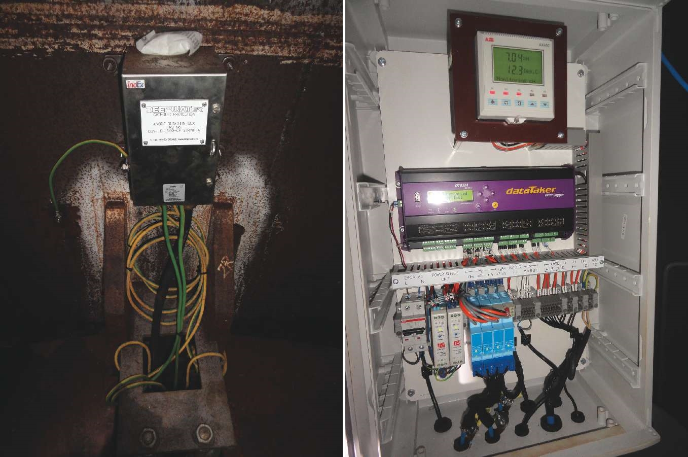
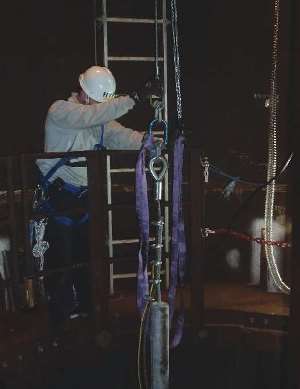 Since one aspect of the trial was to determine the total anode weight needed to meet the CP minimum protection requirement of –800 mV or more negative vs. a silver/silver chloride (Ag/AgCl) reference electrode, four anode strings comprised of six 55-lb (25-kg) aluminum alloy anodes cast on galvanized steel wire rope were installed. Although the CP designers expected that two anode strings would produce the necessary current for CP protection, the other pair of anode strings would be readily available during the trial if needed. For safety reasons, connections between the anode strings and structure were made in a junction box located above the sealed lower platform so the anode connections could be made without entering the airtight column. Initially, only two anode strings were connected to the structure.
Six Ag/AgCl dual reference electrodes, located in two positions at three elevations in the monopile, monitored the structure-to-seawater potential. An additional reference electrode monitored an anode string. Hydrogen sensors and a 1- by 1-m steel plate to measure current density (CD) were installed at the top of the sealed monopile column. The monitoring system also included a pH probe, dissolved oxygen probe, remotely accessible datalogger, and current input monitor to confirm the operation of a ventilation system, which was switched off after a short time period to determine the presence of accumulated hydrogen, one of the major concerns with installing a CP system in an airtight environment.
Trial Results
According to Delwiche and Tavares, a high cathode CD is expected when the CP system is first initialized, then over time the current output from the anodes is reduced and the CD decreases as the structure polarizes. For this CP system, the structure started to polarize as expected, with a high current output initially and then a reduction in current output as the structure achieved more protection (as measured by the CD plate, which was a clean sheet of steel vs. the uncoated, corroded monopile structure).
After two weeks of operation, however, the structure unexpectedly started to depolarize and the structure-to-electrolyte potentials became less negative, which meant the structure was no longer adequately protected. The anode current output and CD also increased, which was unusual because the anode current output and CD were expected to show a time-dependent decrease as gradual structure polarization occurred. The ventilation system had been switched off so hydrogen levels could be monitored, and only insignificant changes in hydrogen were detected. At this stage, a risk of hydrogen build-up in the monopile, which could create a hazardous area within the monopile, was not a concern.
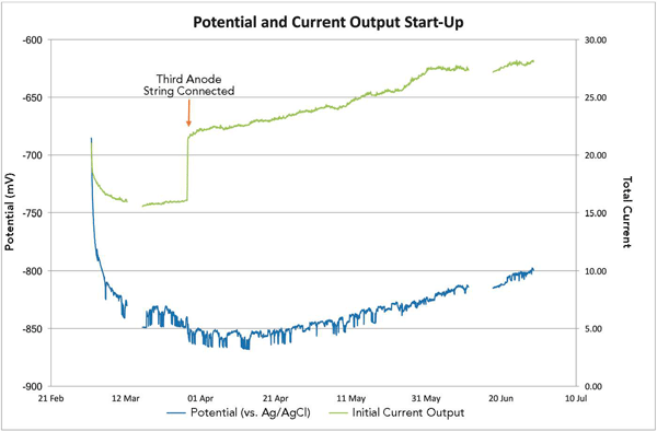
To boost the CP current, Delwiche says, the third anode string was connected to the CP system; however, that only made the results worse. The anode current output and cathode CD continued to increase, which raised concerns about the functionality of the CP system. Two months after commissioning the trial CP system’s two anode strings, personnel were sent offshore to assess the monitoring equipment and take water samples. The monitoring system was checked and found to be fully functional and the readings were verified to be accurate.
When the airtight platform was opened to take water samples, the findings were surprising. The hydrogen sulfide (H2S) alarms were set off and a strong rotten egg smell was noted, which confirmed the alarms were, in fact, measuring H2S. The water had a distinctly blue sheen, Delwiche notes, with whitish deposits seen around the monopile walls that were later thought to be early signs of calcareous deposits. Tavares comments that water samples tested in a laboratory showed very low pH levels—as low as 4.5. Within a 10-week period, the seawater pH inside the monopile had changed from a near neutral pH of 8 to an acidic pH of <5, which was much lower than that for typical seawater.
According to Tavares, the offshore CP retrofit trial had revealed an unexpected phenomenon—the introduction of aluminum anodes inside a sealed wind turbine structure reduces the water’s pH level very quickly. A low solution pH reduces the efficiency of the anodes, he explains, making it difficult for them to produce the calcareous deposits required for adequate CP and also increasing the risk of hydrogen production. Water pH levels at the values observed or the production of toxic and flammable gases (namely H2S) from the operation of a sacrificial CP system when using aluminum alloy anodes had not been previously reported, although trace hydrogen was expected. Aluminum anodes have been used extensively for decades in the offshore oil and gas sector and marine industry—within ballast tanks and platform concrete leg foundations—without any reported concerns relating to changes in water pH, Tavares adds. At the time of the CP trial, issues associated with the use of aluminum anodes in stagnant water conditions were unknown.
The reduction of the water’s pH is believed to be associated with hydrolysis (the chemical breakdown of a compound due to its reaction with water) of the sacrificial anode’s corrosion product. “At the time, we didn’t appreciate what the phenomena was. We were putting more aluminum in the water by introducing the third anode string,” Delwiche comments. He notes that the additional aluminum alloy anodes increased the amount of corrosion product, and the pH of the water decreased as the aluminum ion concentration increased. Although the CP’s electrochemical process produced hydroxyl ions that should have neutralized the acidic conditions created by hydrolysis, the hydroxyl ions also reacted with the buffering salts in the stagnant water to form relatively insoluble calcareous deposits—magnesium hydroxide [Mg(OH)2] and calcium hydroxide [Ca(OH)2]. This reduced the concentration of free hydroxyl ions to a level that was not sufficient to offset the acidic conditions created by hydrolysis of the anode corrosion product.5
A number of options were considered to counteract the low pH within the monopile, including the introduction of chemicals into the stagnant water. Several concerns, however, prevented the project team from executing this solution. Conveying chemicals in either large or concentrated doses can pose a health and safety risk on sea vessels and the transition piece. Additionally, it would be challenging to manage a chemical mixture in an offshore environment, Delwiche says. Ultimately, the solution was to regularly add fresh seawater to the monopile’s stagnant seawater environment. This was done by drilling holes in the seals used on the J-tubes at the bottom of the monopile so the seawater inside the pile was continuously flushed with fresh seawater. The holes were carefully designed to allow a 5% change in water per day and drilled so that the tides, especially the spring tides, did not reach the monopile’s lower platform. After applying this solution on the trial monopile, the flushing technique was implemented on four additional monopiles with favorable outcomes. The CP design was finalized based on the trial results, and work started on retrofitting the remaining wind turbines in the LID wind farms.
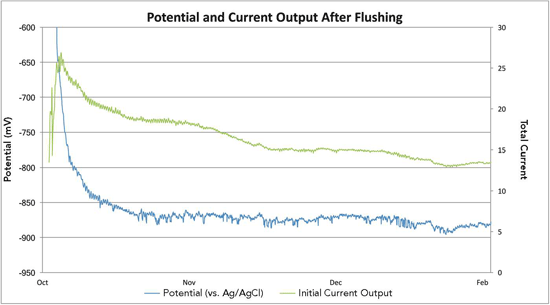
Delwiche notes this solution has proved to be extremely effective, although constant monitoring is required to ensure the fresh seawater flushing continues. Ongoing portable pH checks confirmed that most of the monopiles now have water pH levels above pH 6, which is considered satisfactory, with the majority exhibiting a water pH level of 7. The H2S, which was subsequently found only in monopiles that had a water pH level <6, abated over time when the pH level returned to normal. The trial was extremely valuable in that it established current output requirements and longevity of the anode strings and confirmed the original CP design premise for the monopile, he says.
This article is based on CORROSION 2017 paper no. 8955, “Retrofit Strategy Using Aluminium Anodes for the Internal Sections of Wind Turbine Monopiles,” by A. Delwiche and I. Tavares. Photos courtesy of Alex Delwiche.
References
1 “Offshore wind operational report January-December 2016,” The Crown Estate, June 2017, https://www.thecrownestate.co.uk/ media/1050888/operationalwindreport2017_ final.pdf (June 29, 2017).
2 A. Delwiche, I. Tavares, “Retrofit Strategy Using Aluminium Anodes for the Internal Sections of Windturbine Monopiles,” CORROSION 2017 paper no. 8955 (Houston, TX: NACE International, 2017).
3 A.R. Black, L.R. Hilbert, and T. Mathiesen, “Corrosion Protection of Offshore Wind Foundations,” CORROSION 2015, paper no. 5896 (Houston, TX: NACE, 2015).
4 DNV-OS-J101, “Design of Offshore Wind Turbine Structures” (Høvik, Norway: DNV, 2014).
5 A. Delwiche, P. Lydon, I. Tavares, “Concerns Over Utilizing Aluminium Alloy Anodes in Sealed Environments,” CORROSION 2017 paper no. 8956 (Houston, TX: NACE, 2017).