Electricity is a form of energy generated by friction, induction, or chemical change (electrochemistry), while current is a moving stream of charged particles, principally electrons. The question as to who discovered electricity (and when) is open to question, but it appears to go back ~2,000 years. Clay pots containing an iron rod surrounded by a copper sheet were found in relics from about 27 B.C to 395 A.D. near Baghdad, Iraq.1 The iron rod in the center of the copper sheet was cylindrical at the top and changed to a pencil shape at the bottom, which suggests a bimetallic corrosion cell and that batteries were invented in that era. There is speculation that the silversmiths of Baghdad used these batteries in electroplating small articles.
The word electricity comes from “elecktron,” the Greek name for amber. Amber is a resinous mineral use to make jewelry. In ancient Greece, it was likely that cloth fibers clung to the amber jewelry and attempts to rub them off proved futile due to static electricity. In 1600, William Gilbert used the Latin word “electricus” to describe the force that certain substances exert when rubbed against each other. By the sixteenth century, many electrostatic discoveries were made, including an electrostatic generator.
Benjamin Franklin’s famous kite flying, which generated a spark from a key during an electrical storm in 1752, proved that lightning was a large electrical spark (arc). Investigations into galvanic electricity and electrolytes were completed on frog legs in 1789 by Galvani. Alessandro Volta discovered that certain chemical reactions would produce electricity; and in 1800, he constructed the voltaic pile—an electric battery that produced a steady electric current. In 1812, Sir Humphrey Davy hypothesized that chemical and electrical charges are identical and discovered cathodic protection (CP) of copper using zinc or iron anodes. In 1831, Michael Faraday invented the electric dynamo (a crude power generator) to provide a practical means of generating a continuous supply of electricity.
CP can be defined as a technique for reducing the corrosion of a metal surface by turning that surface into the cathode of an electrochemical cell. In 1902, K. Cohen achieved practical CP using impressed current. Although H. Geppert installed the first CP system on a pipeline in Germany in 1906, it never became popular in that country. In 1928, R.J. Kuhn installed the first rectifier to impress current onto a pipeline in New Orleans, Louisiana, and established the first practical application of CP on pipelines that eventually spawned the formation of the National Association of Corrosion Engineers (now known as NACE International) in 1943.
Although CP is a well-recognized means of corrosion control and the basics are broadly understood, use of the terms “conventional current” and “electrons” can be confused.
Conventional Current or Electron Direction
An electrochemical cell (corrosion cell) consists of an anode and a cathode in an electrolyte connected by a metallic path  training manual.") (conductor) (Figure 1).2 The electrolyte consists of molecules made up of atoms. An atom consists of neutrons (neutral charge), protons (positive charge), and electrons (negative charge). An ion is an atom that has either more electrons than protons and is negatively charged, or has more protons than electrons and is positively charged. Electricity in the electrolyte is due to the movement of ions (Figure 1).
(conductor) (Figure 1).2 The electrolyte consists of molecules made up of atoms. An atom consists of neutrons (neutral charge), protons (positive charge), and electrons (negative charge). An ion is an atom that has either more electrons than protons and is negatively charged, or has more protons than electrons and is positively charged. Electricity in the electrolyte is due to the movement of ions (Figure 1).
Electricity transfer through the metallic conductor is due to the movement of negatively charged electrons. There are no electrons in the electrolyte; electricity transfer through an electrolyte is due to a charge transfer of positively charged ions (cations) moving away from the anode and toward the cathode, while negatively charged ions (anions) move away from the cathode and toward the anode. The direction of conventional current (I) in a metallic path (conductor) is the direction of positively charged particles going from an electropositive potential to an electronegative potential (Figure 2). It appears this convention was started with the original belief that electricity consisted of positively charged particles that later were found to be negatively charged electrons. By this time, however, the convention was established. The direction of the current is determined by noting the polarity on a voltmeter; thus the conventional current direction external to the battery is from the voltmeter contact of the positive terminal to that of the negative terminal.
 In an electrochemical cell, the higher positive potential is the cathode, therefore the conventional current direction is from the cathode to the anode through the conductor (metallic path) and from the anode to the cathode in the electrolyte (Figure 1).
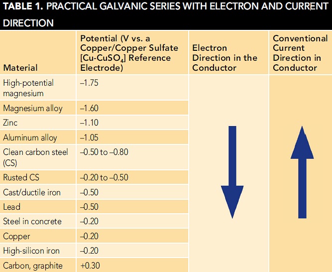
If metals with two different potentials are electrically connected and immersed in an electrolyte, the electrons in the connecting metal (conductor) will travel from the metal with the most electronegative potential to the least electronegative (most electropositive) metal. If using conventional current direction, the current is considered to go from the most electropositive metal to the most electronegative metal in the connecting conductor or from the most electronegative to the least electronegative metal in the electrolyte. Table 13 shows the practical galvanic series with electron and current direction if two metals are connected by a conductor and immersed in an electrolyte.
Current Measurement
A current in a conductor can be measured by a voltage drop across a calibrated resistor (shunt) and is calculated using Ohm’s Law, shown in Equation (1):
where I equals current (A), V equals voltage, and R equals resistance (Ω).
An ammeter, which is a voltmeter with a scale calibrated to an internal shunt to read directly in amperes, can be inserted into the conductor portion of the circuit to directly measure the current. By inserting the ammeter, the external circuit resistance is increased by a resistance equal to that of the internal shunt and wiring. This internal resistance can vary from 0.01 to 1,000 Ω depending on the meter scale, as a lower current scale requires a higher-resistance shunt. In CP, the quantitative amount of current and direction is measured in the metallic path either by an ammeter or a millivoltmeter across an external shunt left in the circuit.
Current Direction
If the current direction cannot be readily measured, such as with a buried or immersed structure, it can be determined by measuring the structure-to-electrolyte potential as the current is applied. A current pickup on the metal surface being measured will result in an electronegative increase in the structure potential when the current is applied (Figure 3).

This measurement should be mandatory when a rectifier is energized to ensure the polarity is correct.
Another source of confusion is the current direction when comparing an offset (side drain) structure-to-electrolyte potential to a potential measurement taken over the structure (i.e., the terminology of “structure-to-electrolyte” associated with a negative value can be puzzling). If the structure is considered to be another electrode, an electropositive potential will indicate a current is going from the structure electrode to the reference electrode, while an electronegative potential indicates the reverse.
 If the offset structure-to-electrolyte potential (Reference A in Figure 4) is more electronegative than the potential of an electrode placed over the pipe (Reference B in Figure 4), this means that the structure is more electronegative with respect to the offset reference electrode (Reference A) rather than the reference electrode over the structure (Reference B), and therefore the offset reference electrode (Reference A) is more electropositive with respect to the reference electrode over the structure (Reference B). Thus, the current direction is from Reference A to B and there is a current pickup indicated on the structure.
Those working in the electronics field will normally think in terms of the electron direction. In CP, rather than talking in terms of the direction of electrons in the conductor and ions in the electrolyte, it is much more convenient to talk in terms of conventional current direction.
However, it is important to distinguish whether the direction is conventional current or that of the negatively charged electrons. A misunderstanding of the current direction can result in accelerated corrosion.
Summary
• Electrons are present only in the metallic conductor and travel from an electronegative to electropositive potential.
• Conventional current direction is from the electropositive to the electronegative metal or measurement points.
• A current pickup on a structure results in an electronegative increase in the structure-to-electrolyte potential as the current comes on the structure (protective), while a current discharge results in an electropositive shift in potential (corrosive).
• A more electronegative structure-to-electrolyte potential measured with respect to a reference electrode placed to one side of a structure—compared to one placed over the structure—indicates a current pickup.
References
1 W. von Baekmann, W. Schwenk, W. Prinz, Handbook of Cathodic Corrosion Protection, 3rd Ed. (Houston, TX: Gulf Publishing Co., 1997).
2 CP1—Cathodic Protection Tester Course Manual (Houston, TX: NACE International).
3 CP2—Cathodic Protection Technician Course Manual (Houston, TX: NACE International).