An oft-uttered phrase by media pundits, politicians, and everyday citizens is "our nation's aging infrastructure." The phrase is typically followed by plans for new structures, complaints about spending (whether it’s spending too much or not enough), or a general statement about how the extremely vague “something” needs to be done. Ultimately, the task of defining and implementing the “something” falls to federal, state, and local government agencies as part of their asset management programs.
These asset management programs face many obstacles for achieving success, which include technical obstacles such as attempting to rehabilitate existing structures and assets to meet the demands of increasing population densities, as well as nontechnical obstacles like budget restrictions, lack of qualified contractors or engineers, and internal knowledge loss from retiring employees. The State of Alaska is no different in these regards, but it does face many additional obstacles, which include extreme climates, limited access to remote areas, and low population densities. The following case examples describe common corrosion problems faced by Alaskan agencies and methods that were used to mitigate those problems in a variety of locations and climates across Alaska (Figure 1).
Case Example 1—Cruise Ship Terminal and Seawall Corrosion Repairs
Southeast Alaska is characterized by its numerous islands and inlets, temperate rain forests that can average over 150 in (3,810 mm) of rainfall annually, and mountains that reach straight into the sea. The natural beauty inherent in this environment drives over a million tourists to the region every year. Most of them arrive via cruise ships, making cruise ship terminals vital structures for the economic health of many southeast Alaskan cities.
The City of Juneau’s Steamship Wharf and adjacent Marine Park serve as a hub for the city’s cruise ships and tourist industry. These structures are a combination of wood, steel, and concrete elements, and range in age from less than one year to several decades. As part of the city’s maintenance plan, they are currently in the final year of extensive corrosion repairs and upgrades that began with initial corrosion remediation recommendations in 2010 and construction in 2016.
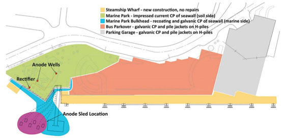
Steel H-piles that support the downtown parking garage and bus parkover were installed in the mid-1980s. The original coating on these piles had failed long ago in the tidal and splash zones, which led to corrosion-induced section loss of the steel. The sheet pile seawall at Marine Park was recoated in the late 1990s. Similarly, this coating failed in the tidal and splash zones. The marine side of the sheet piling is protected with cathodic protection (CP) that utilizes aluminum anode sleds installed in 2000. These sleds are still providing protection to the structure but are near the end of their design life. To protect the soil side of the sheet piles and their tiebacks, an impressed current CP (ICCP) system was designed that includes two shallow anode wells. Figure 2 shows a map of the repairs.
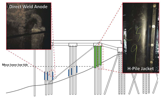
To address the ongoing corrosion of the parkover and garage H-piles, a corrosion plan was developed that included directwelded aluminum anodes and petrolatumfilled pile jackets (Figure 3). Galvanic CP was selected for this work over an ICCP system to avoid the risk of stray current interference from cruise ships. CP requires an electrolyte to provide protective current so corrosion on submerged and buried structures is effectively mitigated. For structures in seawater, the CP system protects submerged areas (with seawater acting as the electrolyte), but provides diminishing protective current in the tidal zone. Because seawater submersion time decreases with increasing elevation, the upper parts of the tidal zone may be left with essentially no CP protection.
In atmospheric environments where CP is ineffective or minimally effective, barrier systems are often employed. These systems can include coatings, galvanizing, wraps, tapes, and jackets. In this case, a petrolatum-filled jacket system was selected due to its longevity; minimal surface preparation requirements; and durability in resisting physical damage from flotsam, a common cause of damage to structures in onshore marine environments.
When designing for any coastal work in southeast Alaska, undoubtedly one of the major factors to consider is the tides. In Juneau, daily tide swings are frequently over 23 ft (7 m). This can create problems for designers—principally it creates problems when designing repairs that are constructible. Extreme tide swings in Juneau means that some high tides submerge portions of the pile caps, making permanent fixed scaffolding and staging impossible. Floating scaffolding needs to be removed before high tides to prevent damage to the pile caps and scaffolding, which creates additional work.
A second obstacle to performing repairs is the seasonal schedule. Work in the winter is impossible for many tasks and extremely difficult for many others. The cruise ship schedule at Steamship Wharf requires any work performed to occur during the narrow spring or fall work seasons when the ships are not in port, or during the summer cruise season when as many as 9,000 passengers travel through the facility daily. This means construction schedules are extremely tight and delays are unacceptable. Additionally, there are no roads to Juneau from the mainland, meaning all supplies and personnel must arrive by boat or plane, which requires diligent planning by the city, contractors, and designer.
The final obstacle encountered is cost. Comprehensive corrosion plans make economic sense for service life, but the money to pay for that work must come from somewhere. Original plans to perform all the parkover and garage H-piles repair work in one project transformed into a phased system that could be budgeted over multiple years. The repairs were prioritized based on need and cost, which led to the addition of the H-pile jacket system and replacement of the sheet pile anode sleds in 2016, the installation of the ICCP system to protect the soil side of the sheet piling in spring of 2018, and installation of the direct-weld anodes for the H-piling and recoating of the sheet piling scheduled in the fall of 2018.
Case Example 2—Bridge Deck Corrosion Damage Due to Deicers
 In contrast to the mild, wet climate of the southeast, the Alaskan interior is characterized by much less precipitation (<11 in [279 mm] on average), warm to hot summers (averaging 62 °F [17 °C] and reaching as high as 100 °F [38°C]), and cold winters (averaging –12 °F [–24°C] and dropping as low as –65 °F [–54°C]). It is the application of deicers during these cold winters that drives corrosion of reinforced concrete bridge decks throughout the region.
Three such bridges were investigated for corrosion damage along Alaska Route 3/George Parks Highway. A battery of tests was performed to assess the current condition of the decking as well as predict future corrosion damage. These tests included potential mapping of the reinforcing steel (ASTM C8761 with 6 in [152 mm] spacing), acoustic sounding of the decking (ASTM D45802), acid-soluble chloride testing of concrete samples (ASTM C11523), corrosion rate measurements via linear polarization resistance (LPR), and Wenner 4-pin resistivity measurements of the concrete surface (AASHTO T 3584).
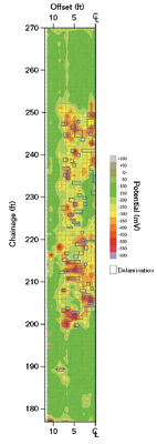
The inspection findings were used to identify locations of active corrosion to be included in bridge deck repairs. Corrosion potential and delamination maps were laid over plan drawings of the bridges to allow the contractor to identify predefined repair locations (Figure 4). As can be seen in the figure, potential mapping helps identify areas of corrosion activity that have not yet resulted in delamination of the concrete from the underlying rebar. This, in turn, assists in defining the repair limits. While extremely electronegative potentials are typically an indicator of corrosion activity, potential mapping works by identifying areas of low potential adjacent to areas of much higher potential. A differential in potential is more indicative of corrosion activity than absolute potential values.1
Corrosion of steel reinforcement in concrete is typically under cathodic control—that is, the corrosion process is limited by oxygen access to the cathode. Even if the chloride content at the anode is sufficiently high for corrosion, corrosion will be slow if readily available oxygen is absent. The soffits of the inspected bridges are covered with stay-in-place galvanized steel formwork. The presence of that steel formwork dramatically limits oxygen access to the bottom layer of reinforcement.
Following excavation and repair of the contaminated concrete, a 0.75-in (19-mm) polyester concrete overlay with a methyl methacrylate (MMA) primer was used as a restoration method. The polyester concrete/MMA primer overlay will significantly reduce future chloride ion penetration into the concrete surface that would otherwise occur from deicer applications.
There is already sufficient chloride ion contamination at the rebar level, however, to facilitate corrosion of steel reinforcement. In areas with relatively thick concrete cover over reinforcement that was passive and not corroding, further diffusion of chloride ions to deeper levels in the concrete will produce corrosion threshold levels in the future even with the presence of the overlay. Oxygen entry to the roadway concrete surface of the bridge deck, however, will be dramatically impeded as well by the polyester concrete/MMA overlay. When the overlay is coupled with the stay-in-place formwork on the bottom of the deck, oxygen availability at the steel reinforcement will be substantially reduced at the level of both rebar mats. Reducing oxygen availability will reduce the rate of any future corrosion.
To complement reduced oxygen availability at the reinforcing steel, small galvanic CP zinc anodes were installed around the repair perimeters. One of the principal criticisms of discrete CP anodes in concrete is that anions (chloride ions in this case) travel through the electrolyte to the anode. When the anode is eventually consumed, this can create a localized environment with high chloride concentrations around each anode, which leads to accelerated corrosion. However, since oxygen access is being significantly reduced by the polyester concrete/MMA overlay on top and galvanized stay-in-place formwork on the bottom, the risk of accelerated corrosion at the anodes once they are consumed is dramatically reduced.
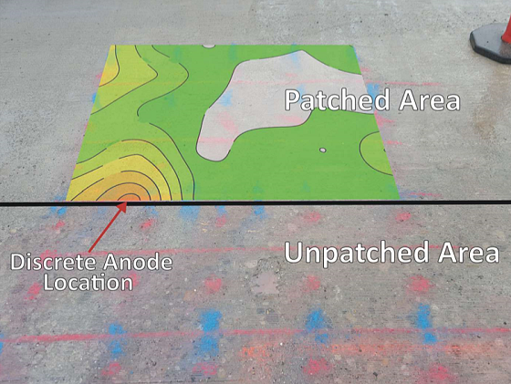
After the repairs were completed, but before the polyester concrete/MMA overlay was installed, LPR corrosion current maps were created over the repairs (Figure 5). These maps show the corrosion activity that would be expected in a region of new, chloride-free concrete with discrete anodes. Negligible corrosion currents were observed throughout the patch, except at the anodes where the high corrosion current of the anode is seen.
Case Example 3— Cathodic Protection System Replacement on a Marine Bridge
The far north region of Alaska is defined by tundra; permafrost; short, cool summers; and long, cold winters. There is a popular adage that Alaska only has two seasons: winter and construction. This is especially exemplified in the city of Nome, which is only a couple hundred kilometers south of the Arctic Circle. Like many towns in northern Alaska, Nome is difficult to access and the construction season is incredibly short (only three to four months long). This makes project logistics critical and work delays unacceptable. Since there are no big box or large contractor supply stores in Nome, a part or tool needed for a job often must be shipped or flown in from a major city—which may delay work for days to weeks.
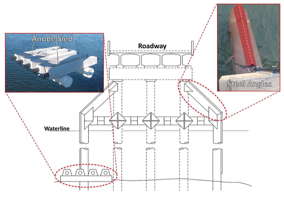
Safety Sound Bridge, located just outside of Nome on Nome-Council Road, joins two narrow spits that separate the lagoon-like Safety Sound from the Bering Sea. The bridge is supported by bare steel pipe piles. An existing CP system had reached the end of its service life and needed to be replaced. Due to the lack of alternating current (AC) power to the site and general remoteness of the location that makes operations checks extremely difficult, a galvanic CP system was selected over an ICCP alternative. This replacement system is composed of aluminum anode sleds attached to each bent on the bridge through test stations accessible from the roadway.
Unlike southeast Alaska, the tides in Nome are typically no more than 3 ft (1 m) and aren’t a major design concern. However, one design concern on this project that does not appear in the southeast are the yearly ice floes that occur when the sound freezes each winter. These ice floes can easily tear apart conduit and hardware attached to the sides of the piling. The original CP system addressed this obstacle with steel channels welded to the sides of the outside piles that were used as a combination ice break and conduit for running anode cables. Not wanting to “reinvent the wheel” with an available working solution, these angles were reused for the replacement CP system (Figure 6).
Conclusions
Durability and maintenance planning in Alaska is not an easy task. Remoteness, low population densities, tight work windows, variable extreme climates, and high costs for materials all factor into well-developed plans. Once in place, these plans must be carefully managed and executed to achieve their goals.
References
1 ASTM C876, “Standard Test Method for Corrosion Potentials of Uncoated Reinforcing Steel in Concrete” (West Conshohocken, PA: ASTM International, 2015).
2 ASTM D4580, “Standard Practice for Measuring Delaminations in Concrete Bridge Decks by Sounding” (West Conshohocken, PA: ASTM International, 2012).
3 ASTM C1152, “Standard Test Method for Acid-Soluble Chloride in Mortar and Concrete” (West Conshohocken, PA: ASTM International, 2012).
4 AASHTO T 358-17, “Method of Test for Surface Resistivity Indication of Concrete’s Ability to Resist Chloride Ion Penetration” (Washington, DC: American Association of State Highway and Transportation Officials, 2015).