Flow assurance problems encountered in the oil and gas industry have become more onerous, leading to increased industry awareness. Hydrate formation is a well-known risk in subsea pipelines and several solutions are available to solve this problem. Adding chemicals, like methanol, reduces the critical temperature where hydrates form. Alternatively, hydrates can be prevented by using subsea pipeline electrical heating technology. Direct electrical heating controls the temperature on the pipeline and offers the potential to significantly reduce operating costs.
Direct electrical heating (DEH), when compared to indirect electrical heating such as electrically trace heating and induction through thermal insulation (ITTI), does not need a large number of heating devices and it is relatively easy to install on subsea pipelines. Furthermore, the DEH method is expected to be an efficient and convenient way to deal with wax buildup in subsea pipelines.
The use of this system is, however, associated with some drawbacks, such as a higher consumption rate of the sacrificial cathodic protection (CP) anodes and the possible risk of alternating current (AC) corrosion. This article presents findings from an investigation and to evaluate the consequences of using the DEH-wet insulation system (WIS) concept on the subsea pipeline to control hydrate and wax buildup.
Direct Electrical Heating Philosophy
During qualification of the ITTI induction system, it was discovered that the heating system could be improved greatly by applying AC directly through the steel wall. A power cable is connected at each end of the pipeline, forcing the electric current through the pipeline steel and generating heat. The heat development in the pipeline is influenced by its electrical and magnetic properties, which varies from different manufacturers, steel grades, and coating condition.

Figure 1 illustrates a general arrangement of a DEH-WIS. At the far-end cable connection point, at the right in the figure, the cable current enters the steel pipe. Part of the current leaves the pipe and is transferred to the sea through the anodes and then returns to the pipe again at the nearend connection point on the left in the drawing.
Following the DEH-WIS success, a similar system was introduced to the subsea pipeline, named a DEH pipe-in-pipe (PiP) system. In this configuration, the pipeline is split into shorter segments that are each heated individually. Figure 2 illustrates a general arrangement of a DEH-PiP system.
In the DEH-PiP system, the high-voltage cable is connected to the production pipe via an electrical connector at the midpoint assembly. The electrical current is then conducted by the pipe wall to each end of the pipeline section. The skin effect and proximity effect keep the current on the outside of the inner pipe and inside the outer pipe, so there is no risk of current leakage to the environment.
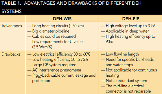
The advantages and drawbacks of the DEH-WIS and PiP are summarized in Table 1. The next section explains the major concerns about DEH-WIS.
DEH-WIS Concerns
In the DEH-WIS, between 20 to 40% of the electrical currents are conducted by the seawater and AC corrosion of the steel pipeline would occur. Sacrificial anodes prevent AC corrosion in the current transfer zone (CTZ) and provide an adequate CP system for the subsea pipeline. The anodes act as effective grounding for the pipeline. Consequently, this will reduce the driving potential and AC density that otherwise could damage the coating in the current transfer zone.
The pipeline’s AC resistance depends on the resistivity and depth of penetration of the magnetic field, which will produce impedance. Research has shown that relative permeability is a crucial factor for carbon steel (CS) pipelines and vast numbers of pipe joint measurements show a substantial difference in magnetic permeability. Consequently, the impedance of the pipe varies along the pipeline and may cause current transfer between seawater and pipe where cracks in the thermal insulation are present. Additional anodes are required at such locations to facilitate current transfer.
The following case study discusses the AC power size for the DEH system, allowable AC current density (CD) for the sacrificial anodes, and additional CP protection CD necessary in designing the DEH system anode numbers and distribution. Furthermore, the magnetic permeability has a tremendous influence on the system, which is also illustrated in the case study.
The pipeline length is 11.5 km. The CS pipeline is made of coated steel; its outer diameter is 0.3 m, the thickness of the pipeline coating is 35 mm, and is installed by rock dumping. The pipeline is made from steel with relative permeability that varies between 400 and 1,600, and the mud resistivity is 150 Ω·cm. The required AC is 1,000 A and the bracelet anode selected is 400 mm long, 30 mm thick, and the outer diameter was aligned with the coating outer diameter.
Al-In-Zn anode material behavior was studied under influence from AC, and there is an indication of reduced anode capacity when AC is introduced.1 For an applied AC CD between 20 to 40 A/m2, the selected electrochemical capacity is 700 A·h/kg.
For CS structures under CP conditions, AC corrosion likelihood should be evaluated considering the level of direct current (DC) polarization. Several reports discussed the effect of IAC/IDC ratio on corrosion rate, and proposed different threshold limits. Having established what was required for the CP of the pipelines, the effects of the DEH-WIS, and to overcome the anode passivation that may occur at high AC,2 increased CDs of 500, 1,000, 2,500, and 5,000 mA/m2, and a cumulative design life of two years for DEH operations was selected.
The conventional CP (without DEHWIS) design capacity required 40 anodes distributed along the length of the pipeline with 300-m spacing. Table 2 demonstrates the CP capacity required considering the DEH-WIS with different AC CDs. The CP design covers a 25-year CP system lifetime, a cumulative two years of operating the DEH-WIS, and considers mean and final pipeline coating breakdown factors, utilization factor, and anode efficiency as well.
The high permeability enhances the skin effect, thereby increasing the power dissipation in the CTZ for a given pipeline current. Kulbotten3 states for a 250-mm steel pipeline, the steady state pipe current is ~64% at a relative permeability of 400 and 48% at a relative permeability of 2,000. It should be noted that the current in the piggyback cable (Icable) returns back in the pipeline (Ipipe), the cable screen (Iscreen), and the seawater (Isea), which means that the total current loss is divided to current loss in the cable and current loss in the sea through the anodes connected in the CTZ.
For Al-In-Zn anodes, pitting of the anode surface increased in quantity and depth with AC level and with a larger area of coupled steel sample. At applied AC densities of greater than or equal to 40 A/m2, large areas of the anode surface were affected.3-4 At currents of 30 A/m2, another work reported significant challenges to the lifetime of the anode due to pitting corrosion,1 while in another, 20 A/m2 was proposed for one year with the value halved for continuous use.5
Table 3 explains the total number of anodes required for each CTZ to meet different CD criteria with a different AC loss percentage in seawater. CTZ length is typically 50 m with an average 2 m separation distance between adjacent anodes. According to the results in Table 3, when the number of anodes is <25, they can be installed in a single arrangement, while more than 25 (i.e., 36, 38, and 50) can be installed in a double/twin anode arrangement.
AC voltage breaks may occur wherever there is a change in the magnetic permeability between successive pipe joints. AC corrosion is believed to be caused by AC flowing from a buried or submerged pipeline to remote earth via a small coating defect in low resistivity soil or seawater. Tests have shown that the worst case size of defect is in the area of 1 cm2. If the defect is too small, the AC takes an alternative lower resistance route. As with any form of corrosion, the lower the circuit resistance, the more corrosion. This is true for AC corrosion. Generally, the resistance of a defect can be determined by Equation (1):
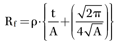
where:
- r: Mud resistivity (Ω·cm)
- Rf: Defect resistance (Ω)
- t: Coating thickness (cm)
- A: Coating defect area (cm2)
A general statement is that there is a risk for AC corrosion on steel if the AC density is higher than 100 A/m2. According to that basis, Table 4 illustrates the electrical fault resistances for different coating defect sizes and the obtained AC voltages.
Furthermore, the operation of DEHWIS can cause stray current corrosion of other structures caused by induced AC voltage. To mitigate this, an exclusion zone is usually positioned around CTZ at each end of a pipeline with a radius of ~30 to 40 m and no structures or pipelines are permitted in this area.
Discussion
DEH-WIS heating efficiency is low as a consequence of the pipe’s low thermal insulation capacity and low electrical efficiency. Therefore, such a system is not a preferred option for high-power requirements.
In Table 2, the number of anodes required in the conventional CP system is the same with increased protection density to 500 and 1,000 mA/m2. However, at higher protection CDs, the required number of anodes is increased, and maximum anode distance is reduced. At extreme protection CD of 5,000 mA/m2, the anode spacing is <100 m and the CP capacity is almost three times the conventional capacity.
Table 3 illustrates how the variation in the relative permeability is a key factor and creates a potential difference to calculate the anode capacity required for each zone, in addition to the maximum AC density limit for the selected type of anode. The best case condition shows that 12 anodes are required for each zone, while the number of required anodes is 50 in the worst-case condition (almost four times of the best case condition status).
Table 4 presents the obtained voltages with different coating defect sizes; for example 6.19 Vac is obtained with a defect size of 1 cm2. This value must be considered during design of the DEH system and the AC voltage profile along the pipeline should be verified to minimize the probability of the AC corrosion. In conclusion, an appreciable ohmic resistance may reduce the risk for AC corrosion.
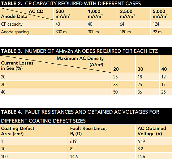
For example, a conventional CP system required only 40 anodes, while total anodes for both CP and DEH systems can be derived from both Tables 2 and 3 with a worst case condition of up to 324 anodes (eight times the required anodes in the conventional case). Results show that the effects of the CP system anodes on the DEH system and vice-versa should be considered.
Furthermore, it should be noted that the outer sheath of the piggyback cable cannot withstand high induced voltage in the screen, so avoiding a high screen voltage to ground in long piggyback cables must be considered. Different methods for solving this problem have been evaluated. A new cable design with a semi-conductive outer sheath has been adopted to enhance the electrical efficiency of DEH-WIS.
What makes the DEH-PiP system complex is that the production pipeline is being employed in a manner similar to high-voltage power cables. There is extruded high-quality electrical insulation around the production pipe, followed by a thin semi-conductive layer, a purity free annulus, and semi-conductive centralizers to safely conduct capacitive charging currents to ground. The major disadvantage is that the most vulnerable electrical component, the mid-line electrical connector, is not reparable.
For comparing the PiP system to WIS, this solution presents higher power efficiency as there is no communication with the seawater. At the outer pipe, the voltage is near zero, so that the current path is clearly defined, maintenance free, and a more cost-effective solution. Finally, Table 1 provides a guideline for the selection based on advantages and drawbacks for each system.
References and About the Authors