There is a saline-alkali soil area of ~340,000 km2 in China, primarily covering the Yellow River delta, western Songnen Plain, Inner Mongolia Autonomous Region, and the Xinjiang Uygur Autonomous Region.1-3 At present, ordinary carbon steels (CS), like Q235 steel or galvanized steel, are mainly used in China as grounding materials in saline-alkali soil. The grounding grid is a significant factor in guaranteeing personal safety, equipment protection, and continuous power supply..4-6 But these two materials are prone to corrosion that can lead to significant economic losses and serious damage when they are buried in the complex soil environments.6-9
Ground rod corrosion prevention measures in saline-alkali soil are generally divided into three methods: 1) find suitable metal materials; 2) transform the environment (such as pH value) of soil; and 3) develop a new conductive anti-corrosion coating. Although widely used in Europe, the copper materials or copper-coated steels have deficiencies as follows when used as grounding grids: first, the copper grounding grids will accelerate the corrosion of adjacent steel frame supports; second, the buried copper will result in severe pollution to the soil and water; and last, there is a shortage of copper as a strategic material in China. Therefore, copper is not a suitable grounding material in China.6 As for the second approach, Ding, et al.10 found that increasing the pH value in soil has a great impact on an anti-corrosion coating, which provides a solution to lessen the corrosion, but it appears to be difficult because the pH value in soil is easily subject to such external factors as acidic rainwater. The third way is the adoption of a new conductive anti-corrosion coating, which can separate the steel grounding metal from the corrosive soil and at the same time change the corrosion potential for the rods and/or grids.4
There are many papers on the application of nickel-based materials in CS to provide corrosion protection.11-12 But there is little research about the water-soluble nickel-rich coatings in saline-alkali soil. With the growing awareness of environmental protection and resources conservation, the development of water-soluble conductive coating is a trend for the times. Nickel-based materials are an attractive option because of their reasonable price and chemical stability. The major objective of this study was to investigate the corrosion resistance of the coating in alkali soil solution and explore the optimum nickel powder content, thus providing a basis for the application of Q235 steel grounding in saline soils.
Materials and Experimental Procedure
Fabrication of Materials
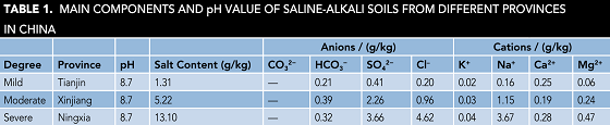
The saline-alkali soil samples were obtained at the depth of 1 m from Tianjin, Xinjiang Uygur Autonomous Region and Ningxia Hui Autonomous Region in China. The soil samples were dried at 105 °C for 8 h in the oven, sieved through 20 mesh sieves, and mixed with deionized (DI) water at a mass ratio of 1:1. Salt content and the main ion content are shown in Table 1, which represent the mild, moderate, and severe saline-alkali soils solution (SASS), respectively.
The coating was prepared by mixing 45 wt% of acrylic resin, 5 wt% of ethylene glycol butyl ether, 8.5 wt% of barium sulfate (BaSO4), 8.5 wt% of strontium chromium yellow, 3 wt% of black paste, 0.4 wt% of ammonium salt dispersant, 0.4 wt% of polysiloxane defoamer, 0.5 wt% of polyurethane thickener, 0.4 wt% of nonionic wetting agent, 1.6 wt% of alcohol amine pH adjuster, 0.5 wt% of other special additives, and 26.2 wt% of DI water. Different amounts of nickel powder (250 mesh) were added, using a mixer at a rate of 4,000 revolutions/min for 30 min. Glass beads were added when stirring the soil and control was maintained of the fineness of the nickel powder slurry below 20 µm. Finally, the glass beads were filtered through a mesh. After that, the conductive and anticorrosive coatings (CACC) were made with the nickel powder content being 10, 20, 30, and 40 wt%, respectively.
The coating was uniformly coated into the surface of the CS electrode by electrostatic spraying, dried for 10 min under natural conditions, then dried in an oven at 50 °C for ~30 min, and finally dried in an oven at 80 °C for ~2 h.
Physical Performance Tests
The film thickness was measured with MiniTest 2100† high-precision coating thickness gauges from ElektroPhysik in Germany. There were 20 points to be measured, with the distance of all the points being >1 cm away from the edges of the plate. Before testing, due to the thinness of the CS sheet and to avoid the large measurement error, larger and thicker iron plates were lined in the back of the CS sheet at the test locations for zero setting and calibration. The maximum and minimum values were removed from each data set and the values of the remaining 18 points were then averaged.
The adhesion force was determined by the guideline, “Paints and varnishes—Cross cut test for films” (GB/T 9286-1998, China).13
Electrochemical Measurements
The conductivity of the coating was characterized through surface contact resistance (SCR), which was tested by digital meter. The electrochemical impedance spectroscopy (EIS) was measured at open circuit potential, with the application of a sinusoidal disturbance signal of 5 mV in the frequency range of 0.05 Hz to 100 kHz. The experiment, made at ~25 °C, was equipped with the 2273† potentiostat/galvanostat from Ametek in the United States. Corrosion mediums were mild, moderate, and severe SASS. The working electrode was Q235 steel (2.5 cm2), the auxiliary electrode being a platinum electrode and the reference electrode being saturated calomel electrode.
Morphology Analysis
The electrodes coated with different nickel-rich CACC were removed after being immersed in different SASS for 61 d. Then, all samples were carefully rinsed with DI water before being inspected using a SXY M-30† optical microscope from Hitachi, Ltd. for morphology analysis of the sample surfaces. The data from the analyses characterized the corrosion products in each different exposure.
Results and Discussion
The testing results of film indicated that the thickness of all coating samples was between 40 and 42 mm. The testing results of the coating showed that the adhesion force can be judged as the rank of 5B, which means a good adhesion force. To derive the optimum nickel powder content in the different types of alkali soil solutions, a series of electrochemical tests were performed.

SCR Measurements
Figure 1 shows the relationship between the SCR of the CACC and the content of nickel powder. Note the SCR of the CACC generally correlates negatively with the amount of nickel powder. When the nickel powder content is <10 wt%, the SCR value of the coating is so high that it is almost an insulator. When the nickel powder content is 10 wt%, the SCR value of the coating is 0.225 Ω/cm2. When the mass fraction increases to 20%, the SCR decreases greatly at first and then decreases gradually while the nickel powder content increases. When the nickel powder content is >20 wt%, the decrease of the surface resistance of the coating is relatively flat.
The researchers discovered from the electrochemical tests that the corrosion resistance of the CS with coated nickel powder is better than that of uncoated CS. With the increase of ion concentration in the SASS, the corrosion resistance of the coating decreased. With the mass fraction of nickel powder increasing from 20 to 40 wt% in the CACC, the corrosion resistance of the coating was worse.

EIS Tests
Figure 2 shows the EIS of the coating with a nickel powder content of 20 wt% immersed in the mild SASS. The chord length formed by the Z-axis crossing the semicircle corresponds to the charge-transfer resistance (Rct) of the coated electrode. The larger the Rct, the greater the radius of the impedance arc, which means the corrosion resistance of the coating is better.14
With the extension of the soaking time, the impedance arc can maintain near the maximum value for a period of time. With the further extension of immersion time, the impedance arc gradually reduced, and the corrosion resistance of the coating decreased accordingly. Figure 3 shows the Nyquist and Bode plots of the non-coated conductive CS electrode soaked in the mild saline solution. Comparing Figure 3 and Figure 2, it can be seen that in the same soaking condition, the corrosive medium is more likely to corrode bare CS, and the coating has a good protective effect on the electrode.

Measurements of Impedance Modulus
In general, it is possible to reflect the corrosion resistance of the coating with the |Z|0.05 value that means the numerical value of impedance modulus at the frequency of 0.05 Hz. At this point, the greater the |Z|0.05 value, the better the corrosion resistance of the coating.15
It can be seen from Figure 4 that for the |Z|0.05 value of the coating, the nickel powder content in 40 wt% is smaller than the nickel powder content in 20 wt%. With the increase of concentration ions in the SASS, the |Z|0.05 value of the coating will decrease. Therefore, the corrosion resistance of the coating is better with a nickel powder content of 20 wt% than 40 wt%. The 40 wt% coating will have a more serious corrosion reaction with the increase of the saline-alkali degree of corrosivity.

Corrosion Morphology
The electrodes coated from different nickel contents were taken out after being immersed in three different soil solutions for 61 d. Then, the surface morphology was observed by an optical microscope, as shown in Figure 5. This indicates that in the same SASS, the corrosion resistance of the coating when the mass fraction of nickel powder is 20 wt% is better than when the mass fraction of nickel powder is 40 wt%.
Meanwhile, Figure 5 also indicates that more bubbles appear on the surface of the CACC if the concentration of ions in the SASS is greater. That means the performance of the corrosion resistance becomes worse in the larger ion concentration. This confirms that the conclusions drawn from the electrochemical tests are correct.
 after being immersed in the SASS with different salt concentrations (mild, moderate, severe) for 61 d.")
Conclusions
To control the corrosion of grounding grids in saline alkali soil, the researchers prepared a water-soluble CACC using high-viscosity acrylic resin and nickel powder. Through the relevant tests, they found that the conductivity of the coating will be better if the mass fraction of nickel powder is greater. However, the highest mass fraction of nickel powder evaluated provided the worst corrosion resistance. When the nickel powder content is 20 wt%, the coating has both good electrical conductivity and enhanced corrosion resistance.
† Trade name.
References
1 S.J. Wang, et al., “Research on Saline-Alkali Soil Amelioration with FGD Gypsum,” Resour Conserv. Recy. 121 (2017): pp. 82-92.
2 H. Xu, et al., “Chinese Land Policies and Farmers’ Adoption of Organic Fertilizer for Saline Soils,” Land Use Policy 38 (2014): pp. 541-549.
3 W.Z. Zeng, et al., “Testing the APSIM Sunflower Model on Saline Soils of Inner Mongolia, China,” Field Crop. Res. 192 (2016): pp. 42-54.
4 Z.X. Ren, et al., “The Protection of 500kV Substation Grounding Grids with Combined Conductive Coating and Cathodic Protection,” Anti-Corros. Methods Mater. 62, 2 (2015): pp. 83-87.
5 V.I. Kostic, N.B. Raicevic, “A Study on High-Voltage Substation Ground Grid Integrity Measurement,” Electr. Ppw. Syst. Res. 131 (2016): pp. 31-40.
6 W. Wei, et al., “Electrochemical Corrosion Behavior of Thermal-Sprayed Stainless Steel-Coated Q235 Steel in Simulated Soil Solutions,” J. Mater. Eng. Perform. 25, 2 (2016): pp. 518-529.
7 R.H. Gong, et al., “Performance Comparison Between Flexible Graphite-Copper Composited Grounding Material and Conventional Grounding Materials,” International Conference on High Voltage Engineering and Application (ICHVE), IEEE, Chengdu, China, 2016.
8 C.C. Qiu, et al., “Corrosion Resistance and Micro-Tribological Properties of Nickel Hydroxide Graphene Oxide Composite Coating,” Diam. Relat. Mater. 76 (2017): pp. 150-156.
9 S. Kim, J.W. Kim, J.H. Kim, “Enhancement of Corrosion Resistance in Carbon Steels Using Nickel-Phosphorous/Titanium Dioxide Nanocomposite Coatings Under HighTemperature Flowing Water,” J. Alloy. Compd. 698 (2017): pp. 267-275.
10 X. Ding, et al., “Influence of Bath pH Value on Microstructure and Corrosion Resistance of Phosphate Chemical Conversion Coating on Sintered Nd–Fe–B Permanent Magnets,” J. Magn. Magn. Mater. 416 (2016): pp. 247-255.
11 S. Suresh, et al., “Evaluation of Corrosion Resistance of Nano Nickel Ferrite and Magnetite Double Layer Coatings on Carbon Steel,” Thin Solid Films 645, 1 (2018): pp. 77-86.
12 T.F. Xiang, et al., “Effect of Current Density on Wettability and Corrosion Resistance of Superhydrophobic Nickel Coating Deposited on Low Carbon Steel,” Mater Design 114, 15 (2017): pp. 65-72.
13 S.L. Guan, “Paint Chemistry and Technology,” Beijing: Chemical Industry Press, 2013 (in Chinese).
14 A.H. Navarchian, M. Joulazadeh, F. Karimi, “Investigation of Corrosion Protection Performance of Epoxy Coatings Modified by Polyaniline/Clay Nanocomposites on Steel Surfaces,” Prog. Org. Coat. 77, 2 (2014): pp. 347-353.
15 H.H. Ge, et al., “A Study of Anti-Corrosion Behavior of Octadecylamine-Treated Iron Samples,” Appl. Surf. Sci. 156, 1 (2000): pp. 39-46.