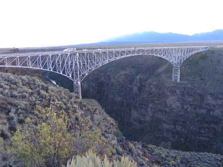
Since 1965, the Rio Grande Gorge Bridge has carried a two-lane highway, Route 64, across the Rio Grande River near Taos, New Mexico. In September 2015, when the iconic landmark reached its 50th year of service, it coincided with the bridge’s biennial inspection that scrutinizes the entire structure for coating failure, corrosion, cracks in the steel, and other structural integrity issues.
The comprehensive bridge inspection was conducted for the New Mexico Department of Transportation (NMDOT) by a Bridge Inspection Program team from the Civil Engineering Department within the College of Engineering at New Mexico State University (NMSU) (Las Cruces, New Mexico). Teams with the NMSU Bridge Inspection Program have inspected the Rio Grande Gorge Bridge since 1973, about the same time the bridge inspection program at the university was first initiated. According to David Jauregui, civil engineering department head and director of the NMSU Bridge Inspection Program, the inspection team comprised four NMSU civil engineering co-op students as well as professionals trained in bridge inspection via rope access and under-bridge access vehicle operation. Undergraduate students performed on-site bridge inspections and were supervised by four professional engineers from NMSU, including Jauregui.
During the assessment, which lasted about a week, the team inspected and rated the physical condition of the bridge’s structural elements as outlined in the U.S. Department of Transportation’s Federal Highway Administration (FHWA) National Bridge Inventory Guidelines.1 This included assessing the condition of the deck, superstructure, substructure, channel, and channel protection for the existing in-place bridge as compared to its as-built condition.
Jauregui notes the team also used the "Manual for Bridge Element Inspection"2 as a guide for condition assessment, which ensures all possible defects on a bridge element are noted during the overall evaluation and incorporated into the inspection results. Two types of bridge elements addressed in the manual are the national bridge elements, which are part of the primary structural components (i.e., deck, superstructure, substructure, and bridge rails) defined by the FHWA national bridge inventory guidelines as necessary to determine the overall condition and safety of the bridge’s main load-carrying system; and bridge management elements, including elements such as joints, wearing surfaces, and protective coating systems, that are normally addressed by bridge preservation practices.

The Bridge Design
The Rio Grande Gorge Bridge is a 1,281-ft (390-m) long cantilever truss structure that looms ~600 ft (183 m) above the surface of the Rio Grande River flowing along the bottom of the gorge. The steel bridge design features three arched truss spans that support a continuous steel grid with a cast-in-place concrete deck. The two ~300-ft (91-m) end spans are connected to the main 600-ft (183-m) truss span and two ~40-ft (12-m) approach spans with a cylindrical pin system. The structure’s horizontal steel members, called “chords,” are supported by vertical steel members connected at diagonal angles to form the trusses. The trusses are supported by two 105-ft (32-m) tall piers sitting on and extending 15 ft (4.6 m) below the surface of lava flows situated ~400 ft (122 m) above the canyon floor. The trusses form steel arches that extend down from the top of the bridge deck ~20 ft (6 m) at the shallowest point in the middle of the center span and ~100 ft (30 m) at the deepest points to the top of the piers. The design also includes several pedestrian viewing platforms that extend several feet out from the roadway. The entire structure comprises ~2,000 tons (1.81 million kg) of steel and 60 tons (54,432 kg) of bolts.3 In 2013, the average daily traffic was estimated to be around 600 vehicles, with trucks comprising 27% of the total.4
The bridge’s previous inspection was done in 2013 by Jauregui’s team, about a year after it underwent a rehabilitation project by the NMDOT that was completed in 2012. As part of the rehabilitation, the top layer of the existing concrete deck was removed with a hydro-demolition process that used highly pressurized water, and replaced with a polyester concrete overlay for a longer-lasting surface. Four hydraulic jacks, each capable of lifting 600 tons (544,320 kg), raised the bridge so old steel bearings could be removed and new bearings installed. Bridge abutment bearings and pedestal bearings were also replaced, and the concrete columns were stabilized and reinforced. Additionally, the project included repainting the hand railings and installing new sidewalks, ramps, curbs, and gutters.5 Prior to the rehabilitation, the bridge was rated as structurally deficient with the deck rated as “poor,” the superstructure as “fair,” and the substructure as “satisfactory.” The 2013 inspection rated both the deck and substructure condition as “good” (seven out of nine), and the superstructure as “fair” (five out of nine).4
Scope of Inspection
During this year’s assessment, Jauregui and his team inspected the concrete deck for cracking, scaling, spalling, leaching, chloride contamination, delamination, and full or partial depth failures. The top-side inspection also included the bridge railing. Because of the height of the bridge and the rocky topography below it, the bridge’s superstructure and substructure elements were accessed from the top of the bridge, which always presents a major challenge when inspecting this bridge, Jauregui says. Fittingly, he notes, the NMDOT had recently acquired an under-bridge inspection unit that enabled the inspection team to gain access to areas underneath the bridge deck and portions of the trusses. This made it safer, faster, and easier for them to inspect the superstructure components—the chords, stringers, arch, trusses, floor beams, gusset plates, and pins on the approach spans—for signs of distress that could include corrosion, cracking, deterioration, section loss, and malfunction and misalignment of bearings. Previously, these areas had been accessed with bridge rigging and bosun chairs that were more difficult to maneuver, and by climbing along the lateral bracing with ropes and tie offs.
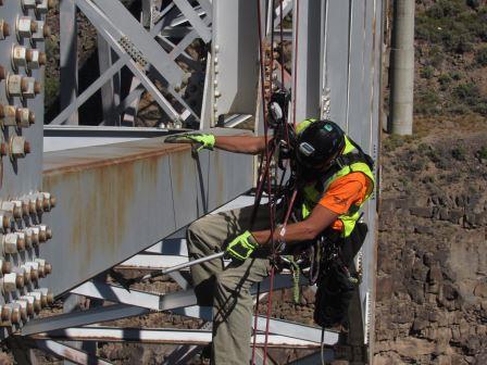
Substructure elements, which include columns, pier walls, and abutments, were also inspected for visible signs of distress such as evidence of corrosion, cracking, section loss, settlement, misalignment, scour, and collision damage. Bridge management elements were assessed as well. These included bearings (moveable and fixed), expansion and assembly joints (with and without seals), wearing surfaces, and protective coatings for the steel and concrete members. Since many areas of the bridge were inaccessible using the under-bridge crane, inspections were also done using rope access techniques by specialized subconsultants (Ayres Associates and Abseilon USA), particularly along the bottom chord and tension diagonals, to get within arm’s reach of those areas of the truss close to the piers.
The inspectors used the National Bridge Inspection Standards (NBIS) rating scale from zero to nine to grade the condition of the bridge components, with a zero assigned for a failed condition (beyond corrective action) and a nine assigned for excellent condition. Also, the "Manual for Bridge Element Inspection" was followed for assigning a condition state for the national bridge elements and the bridge management elements based on the severity of the defects. Condition State 1 indicates an element in good condition, Condition State 2 denotes fair, Condition State 3 signals poor, and Condition State 4 is assigned if the defects are severe, exceeding the limits established in Condition State 3, and a structural review is warranted to determine the strength or serviceability of the element. To rate corrosion on a steel element (e.g., stringer, floor beam, or truss), for example, Condition State 1 would indicate no corrosion, Condition State 2 would indicate freckled rust, and Condition State 3 would indicate section loss. The manual defines freckled rust as initiation of steel corrosion and section loss as evidence of steel loss without impacting the load capacity.
For the protective coating on the steel, the inspectors looked for chalking, peeling or curling, bubbling, cracking, and effectiveness—the degree to which the protection system is functioning to protect the steel substrate.
Inspection Tools
“The main methods of inspection we use are visual and physical,” Jauregui says. Inspection methods used on the bridge deck included chain dragging and hammer sounding, techniques that use sound to detect delamination on the bridge deck. Wire brushes were used to clean debris from the surface of steel members so a visual observation for cracking and section loss could be done. To check areas underneath the truss chords, the inspectors used large mirrors on telescoping poles. Cameras were used to take videos and high-resolution photos of the steel members to verify visual assessments.
During assessment of the superstructure, the inspectors were instructed to look for signs of hydrogen cracking in the welds. “This bridge is fracture critical, meaning that before going out to inspect, we have already identified all the tension members, connections, and fatigue-prone details that need attention to ensure we will be within arm’s reach of them all,” Jauregui says, explaining that the FHWA also issued an advisory6 in 2011 for bridges built in the 1960s fabricated with AASHTO M270 Grade 100 (ASTM A514/A517) (UNS K11576) steel, more commonly known as T-1 steel, which is known to be very susceptible to hydrogen cracking. The advisory noted that during an inspection of the Sherman Minton Bridge, which is constructed of T-1 steel, several cracks were found in the butt welds or their associated heat-affected zones of the tension ties of both spans. It was subsequently determined that the cracking was very likely caused by hydrogen introduced into the weld as the result of improper fabrication procedures.

Data Collection, Storage and Results
For this project, most bridge inspection data were manually collected in the field, with the co-op students documenting the inspection results. Typically, at least two people worked in the same region, Jauregui says, so two sets of eyes were assessing the structure. The inspectors communicated so there was agreement in terms of what they were seeing. To collect data, they were equipped with predesigned inspection sheets that they carried to the inspection sites. Copies of the previous inspection reports were used as a guide for completing the inspection sheets. The preliminary reports were then reviewed by the professional engineers, and the data entered into the AASHTOWare† Bridge Management software used by the NMDOT, accompanied by the supporting photos and video recordings of the bridge elements made during the inspection.
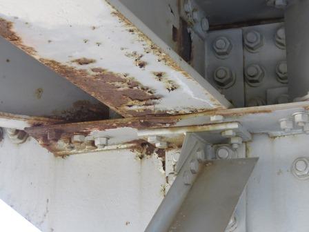
Although the final report on the inspection results was not yet released at press time, Jauregui shared some general observations from the inspection team about the condition of the bridge deck and the coated steel elements. Currently the bridge’s original lead-based coating protects the superstructure from corrosion, which, for the most part, is holding up well considering it’s 50 years old, he says. The atmosphere around the bridge has low relative humidity, and excessive moisture from the river is not a concern; however, snow does fall frequently in the Taos area and the NMDOT uses deicing salts on the bridge deck. Most of the corrosion observed is general corrosion caused by the water drainage system. He comments that the floor beams are showing signs of corrosion due to water run-off from the bridge deck, with the most heavily corroded areas seen at the joint locations where the approach spans meet the main arch truss. Freckled rust has also appeared on the main arch truss. Jauregui notes that water tends to accumulate in pockets created by the gusset plates where the vertical and diagonal steel members of the truss connect to the bottom chords, which leads to corrosion.
The exterior stringers, the bolted connections for the lateral bracing and the sway bracing near the joints, and the gusset plates connecting the truss members are also exhibiting corrosion. The steel stay-in-place formwork (used to construct the cast-in-place concrete bridge deck) has corrosion in isolated areas where the bridge deck had sustained damage and water penetrated the deck overlay. Most likely, Jauregui says, the deicing salts caused some of the damage on the bridge deck and chloride-contaminated water from melting ice and snow contributed to the formwork corrosion.
Another type of corrosion noted during the inspection is fretting corrosion, which occurs at the interface between load-bearing metal surfaces when they are subjected to slight vibratory motion. Fretting corrosion was noted in the connecting plates of the secondary load-carrying members—the lateral bracing and sway bracing—and the gusset plates that connect the main load-carrying members. Jauregui comments that pack rust, which is the accumulation of corrosion product from advanced steel oxidation where the coating has failed, and is “packed” between the plates and causing distortion of the plates, was found under the plates that connect the secondary load-carrying members. The corrosion product adds volume and pushes the connecting plate outward, causing it to deform, he explains, adding that the pack rust was isolated on the secondary members and not seen on the main load-carrying members.

“As far as the level of deterioration, the bridge is holding up quite well,” Jauregui says of the signature bridge. He also comments that the experience of inspecting and assessing the Rio Grande Gorge Bridge has provided the NMSU students with invaluable on-the-job training on how to conduct a bridge inspection, what to look for in an inspection, and how to report the findings so the highway agency can make proper decisions on whether the structure needs to be repaired, retrofitted, rehabilitated, or replaced—crucial skills to possess at a time when aging infrastructure is such a huge issue in this country.
References
1 “Recording and Coding Guide for the Structure Inventory and Appraisal of the Nation’s Bridges,” Federal Highway Administration, report no. FHWA-PD-96-001, December 1995.
2. “Manual for Bridge Element Inspection,” 1st ed. (Washington, DC: AASHTO, 2013).
3. A. Oxford, “A fifty-year span, How the Rio Grande Gorge Bridge came to be,” The Taos News, Sep. 21, 2015, http://www.taosnews.com/news/local/article_666b318e-5d48-11e5-be77-63919bcc85dc.html (Oct. 9, 2015).
4 National Bridge Inventory Data, “US-64 over Rio Grande,” Uglybridges.com, http://uglybridges.com/1371671 (Oct. 9, 2015).
5 C.A. Clark, “Rio Grande Gorge Bridge Project Completed,” Los Alamos Daily Post, Sep. 6, 2012, http://www.ladailypost.com/content/rio-grande-gorge-bridge-project-completed (Oct. 9, 2015).
6 “Inspection of Fracture Critical Bridges Fabricated from AASHTO M270 Grade 100 (ASTM A514/A517) Steel,” FHWA, Technical Advisory 5140.32, September 2011.
†Trade name.