Structures in the Atlantic Ocean coastal water that surrounds Trinidad and Tobago are exposed to five corrosion zones that include Atmospheric Zone, Splash Zone, Tidal Zone, Submerged Zone, and Subsoil Zone.1-3 Corrosion in these zones is an electrochemical process where the seawater or sea salts dissolved in rain or condensed water acts as an electrolyte, and the different potentials between different parts of the steel structure aggravate corrosion.
The rate of the corrosion is driven by many factors; for example temperature, salinity, and time of wetness (TOW). Specifically, this article focuses on aggressive environments off the southeast coast of Trinidad.
Carbon Steel Corrosion Rates In Different Zones
Studies carried out on carbon steel (CS) coupons placed in the different zones on a CS pipe pile in the Atlantic Ocean show where corrosion rates at the different zones lie within the boundaries shown in Figure 1.
Atmospheric Zone
The corrosion rate within this zone depends on the height above sea level. At ~13 m high, the rate is ~0.4 mm/y and this increases to ~0.7 mm/y as it gets closer to sea level. This is due to the sodium chloride (NaCl) entrained in air and sea sprays deposited on the metal due to the wind action. A higher chloride concentration on the metal, with time, accelerates corrosion.
Splash Zone
The highest corrosion rate occurs at this zone, at ~0.95 mm/y. This is due to the high oxygen and chloride content of the recurrent splashing of seawater, which destroys any protective film that might be formed on the steel surface.
Tidal Zone
This zone consists of both high-tide and low-tide regions. In high-tide regions, the corrosion rate ranges from 0.65 to 0.35 mm/y. Low-tide regions have a lower corrosion rate of ~0.15 mm/y, and this is due to a differential cell between the low-tide region and the peak of the adjacent submerged zone. At low tides, when the steel surfaces are exposed to the atmosphere, the corrosion products, iron oxide (FeO), are oxidized to higher oxidation states, resulting in a more noble corrosion potential. Then, when the surfaces are submerged during high tide, the noble region acts as the cathode, with the reduction of the oxides on its surfaces.1-3
Submerged Zone
This zone has a corrosion rate of ~0.35 mm/y. Further down the steel surface, corrosion is governed by the rate of diffusion of oxygen through the water and marine growth present on the metal surface.
Subsoil Zone
At this zone, the corrosion rate is controlled by the availability of oxygen in the soil and depends on whether the soil is considered disturbed or undisturbed. It is also affected by microbial activities. In undisturbed soil the corrosion rate can go to 0.03 mm/y.
Factors that Affect Marine Atmospheric Corrosion Rate
Typical factors that affect atmospheric corrosion rate of structures, platforms, and vessels in a marine environment include:
Relative humidity (RH)— Corrosion rates increase with increased RH. The Trinidad and Tobago marine atmosphere ranges between 80 and 85% RH. The moist, humid environment increases the rate of corrosion by increasing TOWs.
Temperature—Increased ambient temperatures increase the corrosion rates. The temperature during the day in the region are usually in the 30s (°C), which is a high range for atmospheric corrosion of steel in high humidity. Temperature also affects RH, TOW, and dew point.
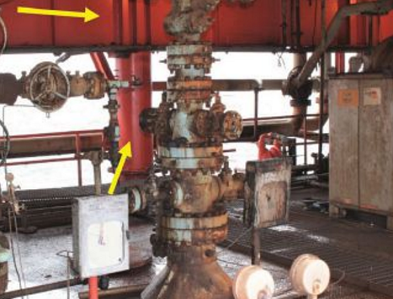
Wind speed—The northeast trade winds affect this region as they bring salt-laden moisture picked up from the ocean spray. The droplets and/or salt dust are then deposited on the metal surfaces (Figure 2) that is in their wind path. Intense corrosion occurs on surfaces facing the prevailing winds, while little or no corrosion occurs in the sheltered areas behind.
Salinity—Seawater in the region has a chloride content of 3.9%, compared to 3.7% in other regions. The higher the salinity of the water, the faster chloride ions succeed in penetrating the protective film.
Types of Corrosion on Structures in Offshore Environments
A study was carried out on structures, platforms, and vessels in the offshore environment of Trinidad and Tobago to determine the types, and prevalence, of corrosion features.
Galvanic Corrosion
Galvanic corrosion was determined to be the most widespread corrosion mechanism observed in this study. The degradation appeared as a continuous layer of corrosion over an entire corroded surface area.4 This type of corrosion occurs when two dissimilar metals are electrically coupled to each other in a common electrolyte, such as a stainless steel (SS) fitting coupled with a CS nut. During galvanic coupling, corrosion of the more anodic metal (CS nut) increases and the corrosion of the more cathodic metal (SS fitting) decreases. The driving force for corrosion is the difference in potentials between the dissimilar metals.
Crevice Corrosion
Crevice corrosion was also prevalent in offshore environments. This corrosion develops from small volumes of stagnant chloride-rich solution present at joints between metallic surfaces4 (e.g., threaded pipes coupled together). Accelerated corrosion occurs at the joint resulting from a potential difference on the metal surface, due to dissimilar environments in contact with the crevice at depth, and with more oxygen near the outer surface. The crevice prevents oxygen from maintaining the passive film, which breaks down and corrosion develops.
Pitting Corrosion
One of the most hazardous forms of corrosion occurs when chlorides remain within droplets formed from seawater that have been entrained in the air. The droplets settle and leave a residue of salt on the surface. This causes a breakdown in the protective film where an anodic area is established. The adjacent cathodic area causes rapid metal dissolution in the pit. As chloride concentrates in the pit, the pH decreases, leading to an increase in the rate of attack in the pit. Pits penetrate and can lead to early catastrophic failure or loss of product. For example, an aluminum crew boat developed pits from the inner side, when the splashing seawater spilled down between the upholstery and the aluminum body of the vessel. It then settled at the cross ribs, and over time broke the passive film and developed pits that penetrated the boat’s hull.
Microbial-Induced Corrosion
Tropical seas are contaminated with microorganisms and bacteria. Aerobic bacteria, including magnesium oxidizing bacteria (MOB), and anaerobic bacteria, including sulfate-reducing bacteria (SRB), tend to colonize metal surfaces and form biofilms.4-5 The SRBs can also survive and flourish on their own in environments where there is no oxygen. Usually the aerobic bacteria create an environment that includes an anaerobic zone below their colonies for SRB to flourish without O2 dioxygen (O2). As the biofilms grows, the bacteria produce a number of by-products, including organic acids, hydrogen sulfide (H2S), and slime. Pitting results from acids and the modified environment of bacteria. The MOB deposits manganese dioxide (MnO₂) as corrosion product like waste, while the SRB deposits iron sulfide (FeS).
Sensitization in Stainless Steel Fittings
SS fittings used in a marine environment are supposed to be in an annealed condition to relieve any internal stresses. When these fittings are welded to other components, the annealed structure around the weld becomes unstable. If left in that state, it becomes susceptible to sensitization. The weldment should be solution annealed followed by quenching to restore the original structure. Sensitization occurs when the carbon migrates to the grain boundaries and combines with the chromium in the region forming chromium carbide, thus weakening the structure. The grains become susceptible to intergranular corrosion or chloride-induced stress corrosion cracking (SCC).4 An example is an SS pipe welded to an SS flange that exhibited branched cracking around the weldment. The structure became sensitized and susceptible to crack propagation, caused by chloride-induced SCC initiated by pits at the surface.
Corrosion Failure Analysis
Case History of Socket Head Cap Screws for Valve
A number of socket head cap screws for a trunnion cap on a ball valve situated on a platform failed prematurely after six years in service. Failure analysis was performed to determine the cause, and to compare the conditions of similar cap screws operating in the environment.
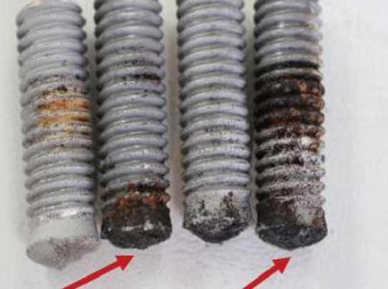
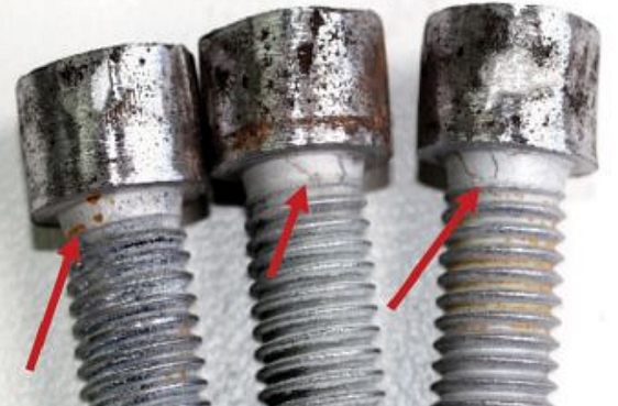
Visual examination of the failed cap screws showed that failure initiated at the interface between the head and shank of the screws (Figure 3). Macro examination showed flaking of the coatings at the shank of the good screws where corrosion was also observed (Figure 4).
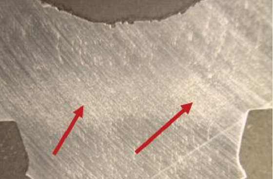
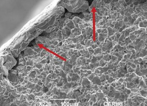
Longitudinal sections through the screws were ground, polished, and etched and revealed a concentrated grain flow at the transition from the head to shank region (Figure 5). Scanning electron microscopy (SEM) fractographs revealed brittle intergranular fracture modes on the surfaces of all screws. Initial cracks propagated from under the zinc coating where grain separation was observed (Figure 6).
Elemental analysis, hardness test, and metallurgical examination showed that the screws from both valves satisfied ASTM A574-17.6 The screws were forged and heat treated to give a quenched and tempered martensitic structure. It was then zinc coated using electrochemical deposition, which gave a coating thickness of 14.26 μm.
Discussion/Conclusion
The cracks propagated at the transition of the head to shank. The Vickers hardness profile ASTM E384-177 measurements taken at two regions on screws displayed higher hardness values; 445 HV1 an equivalent Rockwell hardness of approximately HRC 45 at the head to shank transition with concentrated grain flow when compared to areas 10 mm away that measured 400 HV1, approximately HRC 41.
The x-ray diffraction results on the corrosion deposit identified different phases of FeO corrosion products formed on steel, including akaganeite that contained chloride constituents detrimental to zinc-coated steel.
The failure occurred when the coated socket head cap screws remained in service in the marine environment for a period of time without adequate maintenance. Elemental hydrogen was introduced into the fastener as a by-product of a corrosion reaction from the cathodic reduction process during its service life.
As the coating developed a void (flaking), the difference in potential between the exposed steel and the coating produced hydrogen atoms. The hydrogen atoms then migrated into the steel, thereby embrittling the steel at the grains in the high-stress transition points. It produced a marked increase in hardness values and reduction in ductility that led to embrittlement, which then facilitated cracking in the fastener under stress from the applied torque. This is termed hydrogen-induced SCC. The cracks propagated in an intergranular manner along the lines of least resistance until the screw could no longer take the load and the heads just broke off without signs of deformation.
Recommendations
- It is not wise to electro-plate socket head cap screws to be used in the marine environment; the coating lasts for approximately one year.
- If one is to electro-plate socket head cap screws, one should specify that the core hardness of the screws must not exceed Rockwell C36.8
References
1 C.R. Imbert, W.G. Lewis, “Corrosion of Offshore Platforms Off the South-East Coast of Trinidad,” West Indian J. of Engineering (1999).
2 S. Chandrasekaran, A.K. Jain, Ocean Structures and Material: Construction, Materials, and Operations (Boca Raton, FL: CRC Press, 2016).
3 University Technology Malaysia, “MMB 2713: Corrosion 1,” Marine Corrosion (2010).
4 J.H. Payer, “Eight Forms of Corrosion,” Department of Material Science and Engineering: Materials Engineering Institute (1994).
5 F. Byron, N. Mohamed, C.A. Imbert, “Investigation of the Failure of a Drive Rod on an Offshore Platform Due To Microbial Induced Corrosion (MIC),” International J. of Applied Engineering Research 10, 1 (2015).
6 ASTM A574-17, “Standard Specification for Alloy Steel Socket-Head Cap Screws” (West Conshohocken, PA: ASTM International, 2018).
7 ASTM E384-17, “Standard Test Method for Microindentation Hardness of Materials” (West Conshohocken, PA: ASTM, 2018).
8 T.J. Langill, “Hydrogen Embrittlement Study of Hot-Dip Galvanized High Strength Bolts,” Fastener Technology International April/May (2013).