Florida has more coastline than any state in the continental United States—~1,350 miles (2,172 km) of generalized and over 8,000 miles (12,872 km) of detailed coastline—and no part of Florida is >60 miles (97 km) from saltwater.1 Throughout the state there are more than 12,000 bridges, with over 10,000 of them constructed with either steel-reinforced or prestressed concrete.2 Not surprisingly, thousands of those bridges are located near the coast or cross over water and are exposed to a marine environment.
Steel-reinforced concrete used in bridge structures in marine environments is exposed to chlorides and other chemicals that cause corrosion, which is a leading factor in bridge degradation. As bridge infrastructure deteriorates, the frequency of service calls and cost of maintenance increase. The longer it takes to make repairs, the higher and faster those costs rise. NACE International has estimated the annual direct cost of corrosion for U.S. highway bridges to be $13.6 billion.3
Corrosion costs have compelled the Florida Department of Transportation (FDOT) Corrosion Research Laboratory (Gainesville, Florida) to investigate new technologies and methods that can assess concrete bridge structures for corrosion. In Florida, bridge corrosion issues are found mainly in steel-reinforced concrete substructures (footers, piers, and pilings) near the water, says Adrian R. Steele, laboratory specialist III—corrosion with the FDOT Corrosion Research Laboratory. Corrosion may also occur on the girders of low-lying bridges crossing water near a boat channel, he adds, or on the superstructure of bridges subjected to water spray from personal watercraft and jet boats. For the most part, the state doesn’t experience bridge deck corrosion to the extent that it is seen on bridges in northern climates where deicing salts are on the roads; however, he notes, occasionally bridge deck corrosion will be encountered on structures near a public boat ramp where seawater from towed boats drips on the road surface.
Corrosion of these steel-reinforced concrete structures is primarily caused by chlorides in the seawater, which cause the depassivation of the reinforcing steel bars, Steele explains. Normally, the concrete’s high pH will promote the formation of a protective, passive film on the steel that reduces its corrosion rate. When chlorides diffuse through the concrete and reach the reinforcing steel bars in high enough concentration, however, they destroy the steel’s passive film and leave it vulnerable to corrosion. He adds that chlorides also reduce the electrical resistance of the concrete, which allows the corrosion current to f low more easily.
Steele comments that another type of steel degradation experienced on concrete bridge structures is corrosion of post-tensioning tendons, which are typically made of a high-strength steel bar or several high-strength, seven-wire prestressing steel strands comprised of six small-diameter wires helically wound around a seventh central wire. Post-tensioning tendons can be internal, which are installed through pathways formed by corrugated metal or plastic ducts cast into the concrete; or they can be external and installed inside smooth, high-density polyethylene (HDPE) ducts outside of the concrete. The tendons are stressed with hydraulic jacks, and the annular space around the steel strands in the duct is grouted after stressing. The grout is designed to bond to the steel strands as well as protect the steel from corrosion.4
“We have encountered problems with corrosion in some of these ducts due to issues with the grout,” says Steele. If the duct isn’t completely filled with grout, he explains, the resulting voids or spaces will leave any exposed areas of the steel strands unprotected against corrosion. Also, if the grout doesn’t fully cure, moisture can become trapped in the duct and corrode the steel strands over time. Corrosion of post-tensioning tendons because of faulty grouting can occur in any environment, he stresses, but the problem can be aggravated if chlorides migrate into the voids in the grout.
The obstacle in detecting corrosion of post-tensioned (PT) tendons is that it can be difficult to inspect inside the ducts, particularly those encased in the concrete. “There have been a few failures of the post-tensioning cables when no one suspected there was any problem at all,” Steele adds. “That’s why we’re interested in new technologies—to try and give us some insight into what’s going on inside the ducts so we can properly maintain the bridges.”
The FDOT Corrosion Research Laboratory is working with Mnemonics, Inc. (Melbourne, Florida) to test wireless, passive surface acoustic wave (SAW) sensors for monitoring corrosion of reinforcing steel in concrete as well as PT tendons in grouted ducts.5 These non-intrusive devices could be used for monitoring areas where wired sensor technology may be difficult to install, and may potentially lead to cost savings for bridge inspection and maintenance activities. “We became involved because we are interested in evaluating this technology, and we wanted to see where it’s going and if it is viable—if it is something that would be beneficial to us,” Steele says. “The real impetus for this is that we are looking for ways to detect corrosion in places where we can’t currently inspect, such as inside the post-tensioning ducts.”
Several types of SAW sensors, including temperature, strain, and pressure, have been developed for use in sensing systems. These sensors are small in size, robust, and can respond to external radio frequency (RF) interrogation pulses while embedded in concrete structures. A typical system consists of a wireless transceiver and one or more SAW sensors. The transceiver consists of a digitally controlled RF transmitter/receiver and an interrogating antenna, and a SAW sensor comprises a packaged SAW device mounted on its own antenna. The 10 by 3 by 0.5 mm SAW device consists of a polished crystalline substrate material with two sets of thin aluminum electrodes—the input interdigital transducer (IDT) and the reflector array—deposited on the polished surface.
The transceiver transmits a short-burst RF signal to the remote passive sensors. When the interrogation RF signal is received by the sensor antenna, it converts the electrical signal to a surface acoustic wave that propagates toward the reflector array and is reflected back to the input IDT. The input IDT then reconverts the acoustic signal to an RF electrical signal that is fed to the sensor antenna, and the sensor antenna then retransmits the reflected signal back to the transceiver. Any environmental change within the device, such as change in temperature or pressure, causes a mechanical strain on the sensor’s crystalline substrate that affects the reflected wave propagating on the surface of the crystalline substrate. This strain produces a phase change in the reflected acoustic wave. The acoustic phase change is converted to an RF signal phase change at the input IDT. The sensor antenna then transmits the altered reflected RF signal back to the interrogating transceiver for data processing.
For the test, a standard wireless SAW sensor was modified to operate as a corrosion sensor. This was done by inserting pieces of sacrificial metal (similar in composition to the reinforcing steel bar) as links between the SAW device and its antenna. These links functioned as corrosion detection elements. As the SAW corrosion sensor link corroded, the returning RF signal from the sensor after interrogation would be reduced or eliminated, indicating a certain degree of corrosion.
Five sensors—four sensors with two sacrificial metal links and one without metal links that acted as the control sensor— were embedded in 4 by 8 in (102 by 203 mm) concrete cylinders prepared using a concrete mix approved by the FDOT. The concrete was dosed with sodium chloride (NaCl) to promote conductivity. The cylinders were placed in a saltwater tank and a reverse impressed current cathodic protection system was set up to accelerate corrosion of the sacrificial metal links. Data were collected from the sensors for six months. At the end of the experiment, the sensors were removed and examined. On one corrosion sensor, both sacrificial metal links had completely corroded; and two corrosion sensors had complete corrosion of one link and partial corrosion of the other. The collected wireless RF data predicted the corrosion results observed on the sensors after removing them from the concrete blocks. The fourth corrosion sensor had a wire break during concrete pouring and was examined before the end of the experiment.
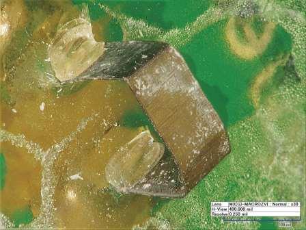
 and a corroded strip (bottom). Photos courtesy of FDOT.")
SAW corrosion sensors that measure strain are also under development, Steele comments. When reinforcing steel bar corrodes, the corrosion products take up a much greater volume than the base metal and generate internal stresses within the concrete. Similarly, as a sacrificial steel coupon in the SAW sensor corroded, it would create stress on the sensor’s crystalline substrate and send back a reflected RF signal that indicated the presence of stress. In the case of a corroded or failed PT tendon wire, the overall stretch of the tendon would change. This change in stretch also could be measured with a strain sensor. “The crystals themselves are sensitive to any change in the length of the sensor itself, so any bending, stretching, or compressing of the crystal you would see in the return signal,” he adds.
Contact Adrian Steele, Florida Department of Transportation—e-mail: Adrian.Steele@dot.state.fl.us.
References
1 Florida Department of Environmental Protection, “Geographical Summary,”
http:// www.dep.state.fl.us/secretary/stats/geographical.htm (Aug. 27, 2015).
2 Material Type of Structure by State (2014), Federal Highway Administration, National Bridge Inventory, http://www.fhwa.dot.gov/bridge/nbi/no10/mat14.cfm (Aug. 27, 2015).
3 Highways and Bridges, “Corrosion Resources for Highways and Bridges,”
http://www.nace.org/Corrosion-Central/Industries/Highways-and-Bridges (Aug. 27, 2015).
4 New Directions for Florida Post-Tensioned Bridges, Post-Tensioning in Florida Bridges, Vol. 1, February 15, 2002, http://www.dot.state.fl.us/structures/posttensioning/NewDirectionsPostTensioningVol1.pdf (Aug. 27, 2015).
5 A.R. Steele, A. Belkerdid, E. Struble, “Passive Wireless Surface Acoustic Wave Sensors for Corrosion Monitoring of Steel in Concrete Structures,” CORROSION 2015, paper no. 6170 (Houston, TX: NACE International, 2015).