Practical post-tensioned (PT) concrete construction was first introduced over 60 years ago and has evolved to become a prime methodology for effecting structural integrity of large reinforced concrete structures. Potential advantages of PT construction include longer spans, reduced construction time, thinner sections with a more streamlined appearance, improved crack control, and overall cost savings compared to structures that are conventionally reinforced. Central to PT construction is the seven-wire strand, where six high-strength, high-carbon, cold-drawn, pearlitic steel outer wires are spirally wound around a central straight wire in conformance with ASTM A416.1 A PT tendon for an unbonded system is comprised of dead and live end anchorages, a prestressing strand, plastic sheathing, and a corrosion-inhibiting post-tensioning coating applied to the strand.
The anchorages are comprised of an anchor, wedges, and ( for encapsulated systems) a cap over the strand tail. Installation involves affixing one end of the strand at the embedded dead end anchor, tensioning the other (live) end with a ram to ~80% of the minimum ultimate tensile strength, and then restraining the strand by inserting wedges at the live end anchor. After relaxation and other losses, stress in the strands is ~65% of their ultimate tensile strength. As such, the sheathing and post-tensioning coating serve as a bond breaker between the concrete and strand. Generally, unbonded PT is employed for high-rise buildings, parking structures, and slabs on grade.
As an offset to the advantages of PT construction, premature tendon repair and replacement have been required in some instances because of strand corrosion. Left unaddressed, tendon failure results. For unbonded systems, corrosion can stem from water intrusion because of inadequate sealing of live end anchorages, concrete cracks inboard of anchorages, or both. This also can be the case for bonded systems, where grout that is physically or chemically deficient, or a combination of these, has been identified as a cause of failure.2-5 This study pertains to an unbonded, PT concrete building structure with extruded sheathing.
Forensic Findings
In response to visually apparent corrosion at live end PT anchors, a number of strands were extracted from slabs for analysis. In cases where strand corrosion was apparent, the attack was generally most advanced within and immediately behind the anchors, and progressively moderated relative to the distance inboard.
Of particular interest are the apparent incidents of corrosion-induced wire disengagement from wedges within the anchors, and the resulting slippage and loss of post-tensioning force. Two examples are cited (designated Tendons 1 and 2) that involve a single wire, and a third (Tendon 3) involves multiple wires. The first two examples occurred during detensioning of those tendons and the third during detensioning of an adjacent tendon. Each of these is discussed in turn.
Tendons 1 and 2
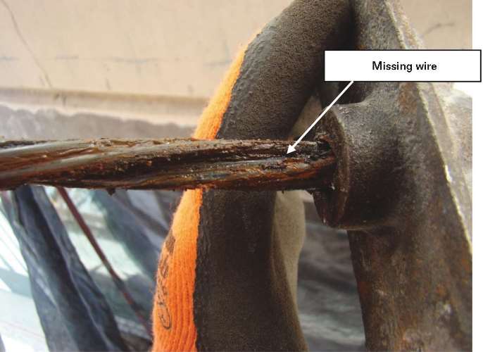
A photograph of the exposed grout pocket of Tendon 1 subsequent to detensioning is shown in Figure 1, which reveals that one of the outer wires is missing. All seven wires were visible prior to detensioning. During detensioning, which involved drilling through the tendon from an exterior soffit, one or more wires were apparently initially severed. This caused the load for the wire in question to increase and exceed the shear strength of its engagement with the wedge teeth. Such a load transfer could occur despite strands being maintained at fixed elongation because of frictional contact between wires, constraint between strand and duct at locations of tendon curvature, or both. Previous studies6-7 have documented such load transfer from broken to unbroken wires. A compounding factor might be reduced confinement forces imposed by the wedges after severing one or more wires.
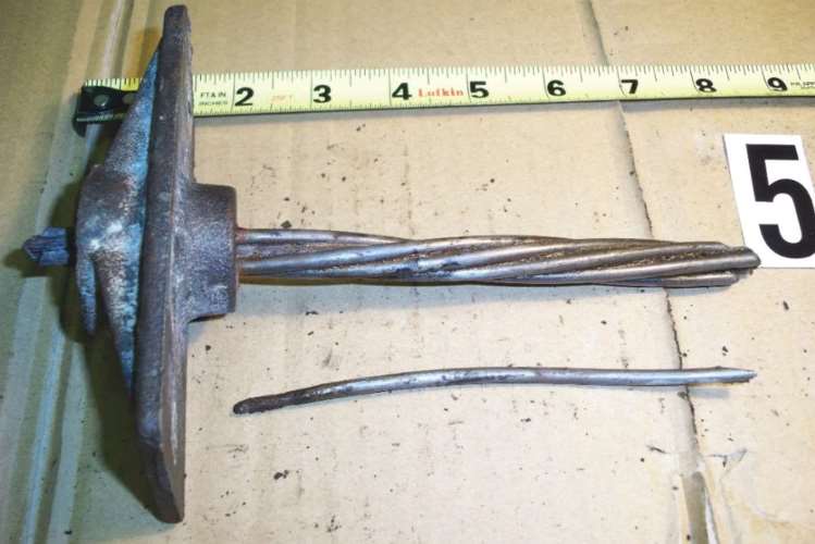
Figure 2 is a photograph of all seven wires and the anchor after cleaning. Because the wires were cut at the same distance inboard of the anchorage, the shorter length of the wire in question is consistent with it having slipped through the wedge teeth and concurrently contracted elastically. Examination of the wedge-wire engagement zone of the slipped wire in Figure 2 revealed shear markings consistent with the wire being dragged along the wedge teeth. The wedge teeth indentations were minimal because of severe corrosion wastage of the wire. Also, one of the wedges from this tendon exhibited corrosion products except for a clean, spiraled path along which the slipped wire apparently contracted.
Examination of the Tendon 2 pocket subsequent to grout removal revealed the same situation as seen in Tendon 1 (one wire missing as shown for Tendon 1 in Figure 1). Figure 3 is a photograph of the strand and anchor from Tendon 2 subsequent to its extraction, with the original position of the slipped wire identified. The same sequence of events apparently occurred here as for Tendon 1—the severing of one or more wires during detensioning, load transfer to uncut wires, and slippage within the wedge grips of one of the uncut wires with severe corrosion at the section within the wedges.
Tendon 3
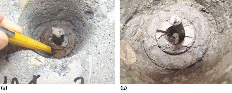
A photograph of the live end anchorage of Tendon 3 as initially exposed, Figure 4(a), shows all seven wires in place, while Figure 4(b) shows this same anchorage approximately four to five months later. Figure 4(a) shows the entire strand in place, whereas only one wire remains in Figure 4(b).
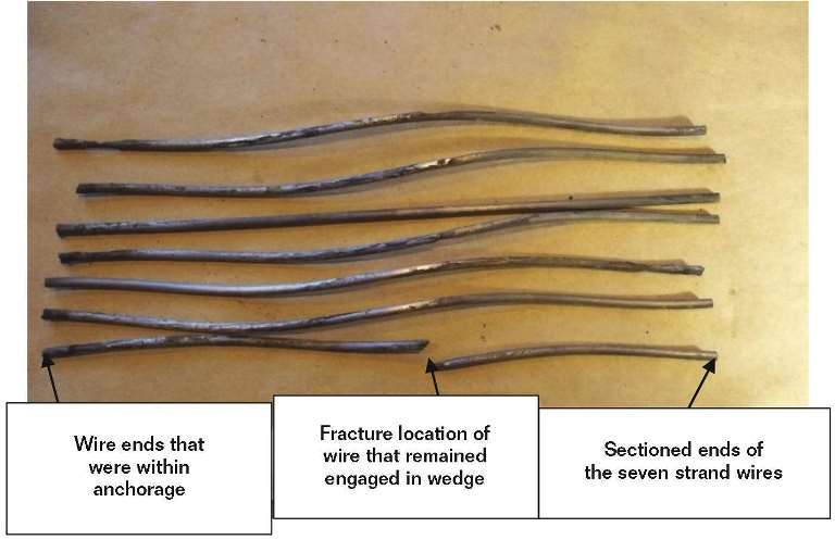
The end portion of all seven wires subsequent to strand extraction and sectioning is shown in Figure 5. Examination revealed the wire that remained engaged with the wedge, shown in Figure 4(b), had fractured ~150 mm from its outboard end in spite of only minor corrosion being present. All seven wire lengths are seen to be approximately the same. Apparently, six wires disengaged from the wedges, either all at once or sequentially, thus transferring the load to the still-engaged wire to the point where it fractured. The outer portion of the fractured wire remained engaged with the wedge teeth seemingly because unlike the other six wires, corrosion of this wire was modest.
In contrast with the wire slippage in Tendons 1 and 2, it is possible that the Tendon 3 slippages occurred on their own accord; however, it is more likely that these occurred in response to an external event. Specifically, a strand in an adjacent tendon was extracted during the four- to five-month time frame between the acquisition of Figures 4(a) and (b). The sudden load release in the adjacent strand may have resulted in a shock wave that caused the six Tendon 3 wires, which were corroded in the wedge zone region, to disengage from the wedges and slip. This, in turn, could have resulted in some of the load formerly borne by the slipped wires being transferred to the remaining engaged wire, which caused it to fracture (as explained for Tendons 1 and 2).
Discussion
On the basis of this study, it is apparent that wire corrosion in the wedge zone can cause disengagement, slippage, load release, and tendon failure. While each of the three cited instances was apparently triggered or facilitated by strand removal activities, the conclusion is that wedge engagement was unstable and slippage imminent, regardless of the conditions that precipitated the events.
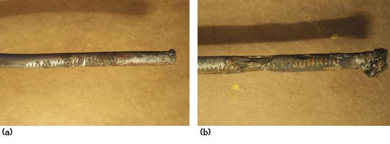
Through the course of the investigation, multiple tendons were extracted for examination of strands and anchors. For the overall population of strands that were extracted, wedge zone corrosion ranged from visually unnoticeable to advanced. For example, Figure 6(a) shows a photograph that exemplifies a case of minor wedge zone corrosion, where only isolated sites are attacked, corrosion products are not extensive, and wedge teeth indentations remain well defined. In contrast, Figure 6(b) illustrates a case of advanced wedge zone attack. As corrosion of the indentations occurred, contact between the wedge teeth and wires was reduced. With sufficient corrosion, shear strength of the remaining wire/wedge teeth engagement can be exceeded and the wires dragged through the teeth, smearing the residual indentations. Corrosion of wedge teeth may also contribute to this failure mechanism.
It is concluded that corrosion within the wedge zone of PT systems is a potential tendon failure mechanism that functions in parallel with inboard corrosion. This failure type can become more significant during a restoration program because vibrations and impact loadings from nearby concrete removal and tendon replacement activities are more prevalent.
Conclusions
A forensic investigation of unbonded PT tendons in a relatively large structure revealed that, in some cases, the portion of wires within anchors had corroded to an extent that engagement strength with the wedge grips was exceeded; and wires slipped inward, thereby reducing force in the tendon. Thus, the slippage of wires within wedge grips is a potential failure mechanism for corroding PT systems. Whether wires slip at wedge grips or fracture at inboard positions is determined by the relative extent of corrosion at specific locations.
References
1 ASTM A416/A416M-12a, “Standard Specification for Steel Strand, Uncoated Seven-Wire for Prestressed Concrete” (West Conshohocken, PA: ASTM International, 2012).
2 T.S. Theryo, W.H. Hartt, P. Paczkowski, “Guidelines for Tendon Grout Sampling and Assessment of Post-Tensioned Bridges,” Federal Highway Administration, FHWAHRT- 13-028, 2013.
3 K. Lau, I. Lasa, M. Parades, “Corrosion Development of PT Tendons with Deficient Grout: Corrosion Failure in Ringling Causeway Bridge,” Florida Department of Transportation State Materials Office, Draft Report, 2011.
4 K. Lau, M. Parades, I. Lasa, J. Radols, “Laboratory Corrosion Assessment of Post-Tensioned Tendons Repaired with Dissimilar Grout,” CORROSION 2013, paper no. 2602 (Houston, TX: NACE International, 2013).
5 K. Lau, I. Lasa, M. Parades “Bridge Tendon Failures in the Presence of Deficient Grout,” MP 52, 11 (2013): p. 64.
6 C. MacDougall, F.M. Barlett, ACI Structural J. 9-10 (2003), p. 581.
7 C. MacDougall, S. Li, PCI J. 9-10 (2007), p. 96.
This article is based on CORROSION 2015 paper no. 5461, presented in Dallas, Texas