Geothermal power stations, which use heat energy from the Earth’s core, are similar to other power stations that use heat from a fuel source to create steam that turns turbines to generate electricity. Because these power plants use steam from a renewable energy source—hot water located below the Earth’s surface—they are considered to be environmentally friendly.
In Iceland, geothermal power is the country’s single largest source of energy.1 Geothermal steam, however, contains noncondensable gases (gases that are not easily condensed by cooling), such as carbon dioxide (CO2), hydrogen sulfide (H2S), hydrogen (H2), nitrogen (N2), methane (CH4), and argon (Ar), that are considered to be either greenhouse, corrosive, or toxic gases. A recent Icelandic regulation with a stricter guideline on atmospheric concentration of H2S, which took effect in 2014, has compelled the country’s geothermal industry to take actions that will reduce H2S emissions into the air.2
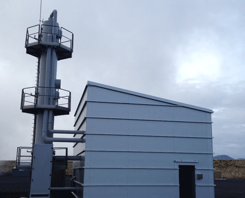
Through a collaboration of universities and Icelandic power companies, an injection abatement project, CarbFix-SulFix, is being implemented at the Hellisheiði geothermal power plant operated by ON Power (Reykjavík, Iceland), a subsidiary of Reykjavík Energy. The Hellisheiði geothermal plant is one of the largest geothermal power plants in the world with a production capacity of 303 MW of electricity and 133 MW of thermal energy. It is located in one of Iceland´s biggest geothermal zones, the Hengill area, which is linked to three volcanic systems.1
The project captures CO2 and H2S emissions from the Hellisheiði power plant in a gas abatement plant that separates them from the noncondensable gas stream using a simple scrubbing process, and then reinjects them in water into reactive basaltic rock at a depth of around 800 m or greater. If these gases were not captured and reinjected, the Hellisheiði power plant would emit ~40,000 tons of CO2 and ~12,000 tons of H2S.3
 Steam ejector vacuum systems are used to extract the noncondensable gases from the geothermal turbine’s exhaust steam. The noncondensable gas stream is sent to the gas abatement plant, which includes a gas separation station that isolates the H2S and CO2 from the other noncondensable gases such as H2, N2 and CH4. The H2S and CO2 are separated by dissolving them in condensed water, says NACE International member Sigrún Nanna Karlsdóttir, associate professor in the Industrial Engineering, Mechanical Engineering, and Computer Science Department at the University of Iceland (Reykjavík, Iceland).
The process pumps the compressed noncondensable geothermal gases (CO2, H2S, H2, N2, CH4, and Ar), which are contaminated with a small concentration of oxygen gas (O2), into the bottom of a ~20-ft (6-m) tall absorption tower, explains Karlsdóttir. Cold condensed water (68 °F [20 °C]) from the power plant is simultaneously pumped to the top of the absorption tower. As the gases flow upward, the water trickles downward through the separation equipment, which facilitates the dissolution of the gases into the water that is reinjected into the basaltic bedrock. The colder the water, she notes, the more soluble the H2S.
When H2S and CO2 gases are dissolved in geothermal fluid, the corrosive nature of the gases and other process factors, such as the pressure, flow rate, and pH level of the liquid containing the dissolved gases, can cause corrosion in geothermal equipment and wells that may lead to failure. In addition to general and localized corrosion, H2S also can cause hydrogen-induced cracking (HIC), stress corrosion cracking (SCC), and sulfide stress corrosion cracking (SSCC). Karlsdóttir comments that the gas separation station in the initial pilot plant had considerable uniform and pitting corrosion problems that stemmed from the construction material used—carbon steel (CS). Because the gas separation station is a crucial component of the abatement process, it was extremely important that the gas separation station in the larger-scale plant would perform without major corrosion issues. This meant that a more suitable material needed to be selected for the plant’s construction.
Materials Selection
The material chosen for the construction of the absorption tower and piping in the larger-scale gas separator was austenitic stainless steel (SS) UNS S31603. Karlsdóttir comments that austenitic SS is the most widely used class among SS. Austenitic steels contain Cr and Ni, which render a compact, passive surface film that resists corrosion in corrosive environments. UNS S31603 also contains 2 to 3% Mo, which makes it more resistant to pitting corrosion. It also contains a lower amount of C (< 0.03%) to decrease the risk of intergranular attack in the as-welded condition or in short periods of high-temperature exposure (from 788 to 1,490 °F [427 to 816 °C]).
Austenitic SS is commonly used in the oil and gas industry where H2S is present, Karlsdóttir says. She notes that some research has been done on SCC and SSCC of UNS S31603 in environments that contain H2S, CO2, and chlorides, and both H2S and chlorides were found to promote and accelerate general corrosion and SCC. UNS S31603 in geothermal environments was also studied, and pitting corrosion was observed in laboratory experiments in geothermal brine at 140 °F (60 °C) with a pH of 4.7, and SCC was also reported at 140 °F. The temperature in the abatement system’s larger-scale gas separation station, however, is considerably lower at ~20 °C, and chloride ions are not expected to be in the environment. However, oxygen is present, which can accelerate corrosion in a geothermal environment.
Corrosion Study
To evaluate the corrosion resistance of the absorption tower, which is in contact with high concentrations of H2S, Karlsdóttir and her colleagues at the University of Iceland and the Innovation Center Iceland conducted a study4 on the corrosion behavior of UNS S31603 while being exposed to the H2S cleaning process in the absorption tower. Karlsdóttir was the chief investigator of the corrosion testing in the tower. The project investigated the steel’s resistance to uniform and pitting corrosion as well as its susceptibility to SCC. Other materials—CS (S235JR), austenitic SS (UNS S30403), and duplex SS (UNS S31803)—were also investigated for comparison.

The round corrosion coupons used for testing, 45 mm in diameter with an 11-mm hole in the center, were cut from 3-mm thick plates of S235JR, UNS S30403, UNS S31603, and UNS S31803. Before testing, the specimens were cleaned and weighed. Three coupons for each material tested were threaded onto a specimen holder, with a 15-mm space between them and separated with a plastic material (polyoxymethylene). To study the likelihood of UNS S31603 cracking in the high H2S concentration, the ASTM G30-97(2016)5 U-bend test method was used. Test specimens, 90-mm wide by 15-mm long by 3-mm thick, were cut from UNS S31603 plate, with the longitudinal direction parallel to the rolling direction of the steel plate. All specimens were bent around a predetermined radius of 15 mm with a custom made U-bend machine capable of providing single-stage stressing.
The specimen holder was inserted in a valve located near the middle of the tower, where the H2S concentration is midway between the lowest and highest concentrations, to get test results that represented an average for the tower, says Karlsdóttir. After four and 12 weeks of testing, the specimens were removed, cleaned, weighed, and evaluated for corrosion. For each material, the microstructural and chemical composition of a specimen’s surface and cross-section were analyzed with scanning electron microscopy (SEM) and x-ray energy dispersive spectroscopy (EDS). The corrosion rates were calculated per ASTM G1-03(2011).6

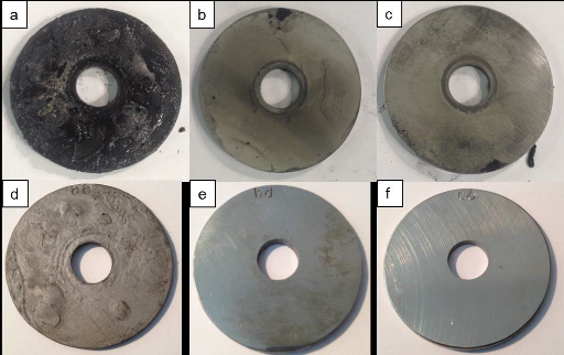
The UNS S31603 and S31803 SS samples held up quite well in this experiment. “They performed as expected,” Karlsdóttir comments. The corrosion rates were negligible and no corrosion damage was detected in the microstructural analysis of the cross-section of either the UNS S31603 or the S31803 SS samples after four and 12 weeks of testing. The UNS S31603 U-bend specimens did not experience SCC, and cracking or pitting was not detected in the tested specimens. The results of this test indicate that S31603 is a sufficient material choice for the absorption tower. “Because of the low temperature, UNS S31603 is a pretty safe selection for this system,” Karlsdóttir says, adding that a longer testing time is advised to support that conclusion. She notes that SCC would be more likely to occur with UNS S31603 if the temperature was higher.
In the UNS S30403 SS samples, stress corrosion cracks were starting to form. Since this SS grade does not contain Mo, Karlsdóttir explains, it is more susceptible to localized corrosion such as SCC and pitting when exposed to H2S.
The S235JR CS samples exhibited poor performance during the test, with a significant amount of corrosion damage and a high corrosion rate—4.2 mm/y and 3.0 mm/y for four and 12 weeks respectively, which is considerably higher than the acceptable limit of 0.1 mm/y.

Although Karlsdóttir expected the CS to corrode, she was surprised at the degree of blistering and HIC that was observed—particularly for the four-week test, a relatively short testing time in the absorption tower. The researchers acknowledge that wet environments containing H2S and/or CO2 along with oxygen contamination can be very aggressive to carbon and low-alloyed steels. Internal blistering, HIC, and stress oriented hydrogen-induced cracking (SOHIC) of CS in the presence of very high H2S concentrations have been associated with wet H2S environments.
The study confirmed that the selection of UNS S31603 for the absorption tower was a good material pick, Karlsdóttir comments. “It verified that it was the right decision not to go with a lower-grade material like UNS S30403 because cracking was detected, indicating its susceptibility to SCC in the system,” she says. The research also shed light on what happened to the CS components in the first pilot plant: the availability and aggressiveness of the H2S along with the presence of oxygen caused the corrosion damage. “The environment really requires the use of UNS S31603,” Karlsdóttir concludes. “It is not expensive compared to higher grades of corrosion-resistant steels. It was a good choice.”
More information on the study can be found in the CORROSION 2016 paper, “Corrosion Testing in H2S Abatement System at Hellisheidi Geothermal Power Plant in Iceland,” by S.N. Karlsdóttir, S.M. Hjaltason, and K.R. Ragnarsdottir.
References
1 “Basic facts about geothermal and renewable energy in Iceland,” Geothermal Energy, ON Power, http://www.onpower.is/geothermal-energy (February 16, 2017).
2 “Tackling the Challenge of H2S Emissions,” ON Power, https://www.on.is/sites/on.is/files/on_h2s_presentation-australia-new.pdf (February 16, 2017).
3 “The CarbFix Project,” Orkuveita Reykjavíkur (Reykjavík Energy), https://www.or.is/english/carbfix-project (February 16, 2017).
4 S.N. Karlsdóttir, S.M. Hjaltason, and K.R. Ragnarsdottir, “Corrosion Testing in H2S Abatement System at Hellisheidi Geothermal Power Plant in Iceland,” CORROSION 2016, paper no. 7568 (Houston, TX: NACE International, 2016).
5 ASTM G30-97(2016), “Standard Practice for Making and Using U-Bend Stress-Corrosion Test Specimens (West Conshohocken, PA: ASTM, 2016).
6 ASTM G1-03(2011), “Standard Practice for Preparing, Cleaning, and Evaluating Corrosion Test Specimens” (West Conshohocken, PA: ASTM, 2011).