According to the World Health Organization,1 it is estimated that currently 1.1 billion people across the world do not have access to safe drinking water and more than twice that number are without adequate sanitation. The use of unhygienic quality of water is the root cause for 80 to 90% of all diseases in developing countries. Having a reliable source of fresh water for the future is of high priority. The need for a reliable source of fresh water requires a technology that extracts fresh water by removing saline (salt) from bodies of salt water. Desalination is being increasingly realized as the answer to the water crisis of the 21st century.
There are three main processes used in desalination plants, the oldest of which is multi-stage flash, where the seawater is essentially boiled at low pressure and the steam that flashes off is condensed for drinking water. The second process is multiple effect distillation, in which low- pressure steam is used to force evaporation of seawater and the vapor is then condensed for drinking water.
The third process is seawater reverse osmosis (SWRO), where chloride is selectively removed from water by forcing it at high pressure through a semi-permeable membrane. SWRO plants require no heat, but they do require significant quantities of electricity to drive all the high- and low-pressure pumps. Energy costs are a major factor in the development of these plants. Some recent plants have constructed large solar arrays in the desert or have installed wind farms, so that they are powered by renewable energy.
All three of these methods have advantages and disadvantages.
Advantages of SWRO
SWRO desalination plants are found in the Middle East, and anywhere else there is a need for fresh water, such as holiday islands, Australia, Southern United States, and arid regions, such as Spain, Israel, and North Africa. They have the advantage that they can be turned on and off relatively simply, and they can be constructed in a wide range of sizes, as shown in Figure 1, where the capacity is usually measured in m3/day. SWRO plants can also be modularized, so that extra trains can be added as water demand increases. Because of this, most of the new desalination plants currently being designed and built are SWRO.
Growth of SWRO
The increase in demand for water is clearly shown by the statistics for the new build water production capacity over the last 10 to 20 years. Figure 2 shows the new build capacity from 2006 to 2019, indicating the prevalence of SWRO.2

SWRO plants can be small, such as those for hotels, hospitals, and golf courses, while those for public utilities are large. Typical capacity for a public utility is 200,000 to 300,000 m3/day. The larger plants are ~600,000 m3/day. A typical SWRO plant of ~250,000 m3/day uses ~250 tons of stainless steel (SS), the vast majority of which is now super duplex SS. In addition, polymers are widely used for piping for both the seawater intake and the final drinking water, and carbon steel (CS) with coatings is required for the infrastructure.
The U.A.E. has ~3.2 million m3/day of SWRO production and it has contracted an additional 780,000 m3/day from 2019 to 2025 (25% growth).2 This is just the U.A.E. and similar growth is forecast for Saudi Arabia and the rest of the Middle East. Growth is also forecast for Australia and the United States, but not on the same scale. However, the total world growth in SWRO is forecast to be ~8%/y up to 2025.2 There are at least 200 planned new build SWRO plants over the next 15 years. None of this includes the building of small scale plants (for hotels, etc.) or that for existing plants that might add extra production capacity.
Principle of SWRO
The principle of reverse osmosis is simple. If a low-chloride and a high-chloride water are separated by a semi-permeable membrane, water will transfer through the membrane from the low-chloride side to the high-chloride side. This process is called osmosis. The transfer of water in one direction then builds up a net pressure on the high-chloride side, which is called the osmotic pressure. If a pressure is applied to the high-chloride side that exceeds the osmotic pressure, then water will transfer faster from the high-chloride to the low-chloride side. This process is called reverse osmosis, and the transferred water is relatively pure compared to the original brine.

Commercial units use a whole series of membranes, which consist of either a sheet-like membrane wound around an inner core, or numerous hollow fine fibers laid in parallel, and they selectively block the transfer of chloride ions. The membrane cells are used in series and parallel to produce the required water quality. Reverse osmosis is most commonly used to remove the chloride from seawater, but it may also be used to purify brackish waters of lower, or brines of higher chloride content.
In the last 20 years there has been a big improvement in the efficiency of the membranes and a reduction in the cost. This is one of the reasons for the popularity of SWRO for desalination.
A Typical SWRO Plant
Most SWRO plants follow the same type of layout, as shown schematically in Figure 3. They can be divided into four sections. The first is the low-pressure seawater intake, where the maximum pressure is 1 MPa and the seawater is filtered and treated. This is necessary because the membrane cells are the single highest cost item in a reverse osmosis plant, and it is important to prevent degradation of the membranes to extend their life. The seawater may have chlorine and/or hypochlorite (ClO-) injected near the seawater intake to prevent fouling. It then passes through coarse filters to remove plastic bags, fish, and other large items.
The seawater is then usually dosed with a chemical to aid coagulation as it passes through the dual media filters. These are large vessels with layers of various materials to remove organic matter and other material from the seawater. Finally, the water is fine filtered through cartridge filters to ~1 μm.
Before the high-pressure pumps, depending on the pH of the feedwater, it would be normal to add an antiscalant to limit precipitation of calcium and magnesium salts. Chlorine and/or hypochlorite is a powerful oxidizing agent and it will cause damage to the membranes, unless it is removed. This is usually done by monitoring the redox potential and dosing with sodium metabisulfite (Na2S2O5) to bring the redox potential down to an acceptable value. It is also common to add a nonoxidizing biocide to limit organic fouling of the membranes.
The second or high-pressure section can operate from 6 to 10 MPa, with 7 MPa being a typical value, while high-recovery systems may operate closer to 10 MPa. In the membrane cells chloride is removed in two or more passes, depending on how pure the final water must be.
After chloride removal, the third section handles the permeate (pure water) and is ~0.1 MPa pressure and it is then pumped to storage or a distribution system. Although this is low pressure and low chloride, it is quite corrosive because the water has little tendency to form protective scales of calcium carbonate (CaCO3).
The fourth section is the reject brine section, where the chloride concentration may be twice that in natural seawater. The pressure is still high (~6.9 MPa) and this energy is not wasted, but is hydraulic energy recovery, which transfers hydraulic energy from the brine directly to the feedwater either just prior to or just after the high-pressure pumps. There are two types of energy recovery device, the centrifugal type and the isobaric type. The energy recovered reduces the power of pump required and is much more efficient than electricity generation.
Corrosion Issues
The low-pressure section is essentially a typical seawater handling system, and uses materials found in many seawater cooling systems. Fiber-reinforced plastic (FRP) tends to be used for large-diameter feed pipes, and high-alloy SS (super duplex or 6% molybdenum austenitic) for metallic pipes, pumps, and valves. Vessels, such as the dual-media filter vessels, are usually neoprene-lined CS. The two main corrosion problems have been pitting and crevice corrosion through using a lower alloyed SS, such as Type 2205 duplex (UNS S32205), and pitting due to poor heat treatment in manufacturing, causing precipitation of sigma phase, as shown in Figure 4. Sigma phase greatly reduces the corrosion resistance.

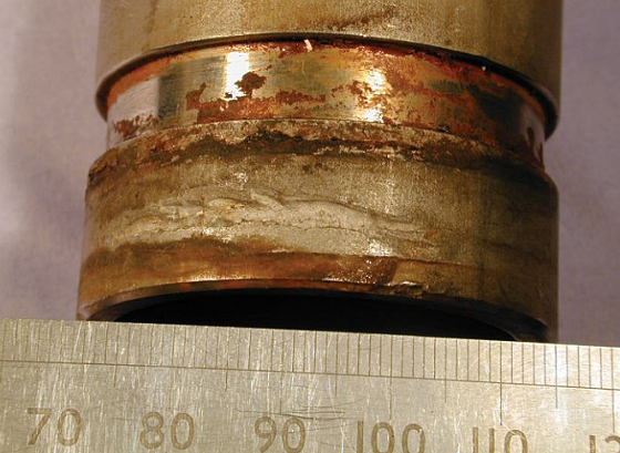
In the high-pressure section, the membrane vessels are usually FRP, while the pumps and piping are mostly super duplex SS because it is lower cost than 6% Mo austenitic. Again, there have been crevice corrosion problems in plants that have used lower alloy SS, and occasional leaks at welded joints due to excessive heat input and/or interpass temperatures. The main joints in the high-pressure section are not flanges, but high-pressure couplings, as recovered prior to discharge. Traditionally, this was done using a Pelton wheel, or similar device, generating electricity from the reject brine. However, modern plants tend to use shown in Figure 5. The seal is often neoprene or ethylene propylene diene monomer (EPDM), and it creates a tight crevice on the outside of the pipe. This can cause severe crevice corrosion and leakage if the pipe material is not sufficiently corrosion resistant, as shown in Figure 6.

The drinking water tends to be handled by Type 316L SS (UNS S31603) piping or a polymer. The polymer must be approved by the U.S. Food and Drug Administration, or national equivalent, if the water is for drinking. These materials rarely give corrosion problems.
The reject brine section commonly uses ceramics and super duplex SS for the hydraulic energy recovery devices and super duplex for the piping. FRP may be used for the reject brine disposal after the energy recovery devices. Corrosion problems are rare in this section, unless a low-alloy SS is used.
Corrosion engineers are clearly needed in the desalination industry to not only ensure that the correct alloys are selected, but that proper technical specifications, including quality assurance and quality control, are in place to ensure the material delivered is fit for service.
References
1 “Water Scarcity,” World Health Organization, https://www.unwater.org/water-facts/scarcity (June 2020).
2 Global Water Intelligence/Desaldata, www.desaldata.com (Jan. 2020).
Bibliography
R. Francis, Avoiding Corrosion in Desalination Plants (Houston, TX: NACE International, 2019).
R. Francis, “Avoiding Corrosion in SWRO Desalination Plants,” Materials Performance webcast, http://www.materialsperformance.com/webinars/roger-francis (May 2020).