In this study, the explosion failure of a bellows expansion joint made of Type 304 stainless steel (UNS S30400) in a pipeline conducting methane (CH4) gas at 400 °C is analyzed. Using the simulation mechanical software, the behavior of the pipeline during the working condition was investigated.
Observations of the metallographic sections indicated that corrosion was involved in the cracking of the bellows that led to the explosion. After investigating the fracture surface, it was noted that the cracks occurred at dimples in the bellows. The presence of hydrogen sulfide (H2S) in the gas stream resulted in stress corrosion cracking.
Today, bellows expansion joints are broadly used in pipelines to dampen vibration and allow thermal expansion. Their application is in oil refineries, chemical industries, cooling and heating systems, and nuclear power plants. Bellows usually are made from relatively thin stainless steel (SS) strips and are corrugated to provide the essential elasticity required to damp the thermal and mechanical motions that occur in the pipelines.1-6
These bellows are manufactured with a variety of forming processes, with roller forming, pneumatic, and hydraulic tube forming being the most popular manufacturing processes employed.7-9
There are many groups of bellows joints, including simple, universal, gimbal, hinged, pressure-balanced, and elbow type, assembled in a variation of convolution forms such as C, S, and U shapes, which are the most popular configurations.2
Employing different kinds of convolutions in the bellows, U-shaped expansion joints can damp absorptions and can be used as a necessary component in pipelines. Significant research has been conducted on low-cycle fatigue life for these bellows joints according to the standards of the Expansion Joint Manufacturers Association, Inc. (EJMA), one of the most authoritative in this field.10
This study is the result of the numerical and experimental investigation of an accident that occurred with a U-shaped Type 304 SS (UNS S30400) expansion joint that was damaged from an explosion in a gas line at 400 °C. This expansion joint was a conduit for a methane (CH4) gas line and was made with 1.8-mm thick cold rolled strips of Type 304 austenitic SS sheet without any post-weld treatments. The design temperature for the default working condition was 400 °C and the accident occurred after eight months of service. The gas composition flow through the pipeline was CH4 and ~60 ppm of hydrogen sulfide (H2S) with a pressure of 600 KPa. The microstructure, fractography, and corrosion of the unsuccessful material were observed using scanning electron microscopy (SEM) and optical microscopy. Also, by using mechanical simulation software, the behavior of the pipeline during the working conditions was investigated.
Experimental Procedures
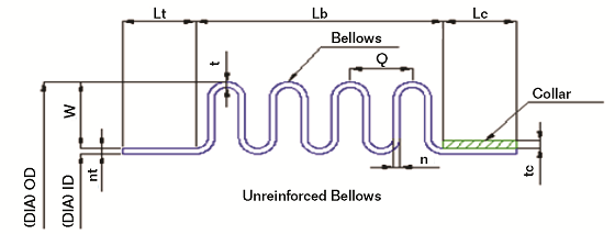
A partial section view of the expansion joint is shown in Figure 1. According to Figure 1, this kind of expansion joint has two bellows at both sides and can absorb mechanical and thermal movements properly. Referring to Figure 1, the outside diameter (OD), inside diameter (ID), W, and q are 762, 752.5, 29, and 32 mm, respectively. The material used for the bellows was AISI 321 and the number of convolutions was six.
To study the cracks that accrued in the Type 304 SS bellows sheet, both the up and downstream sheets were investigated. Figure 2 shows the actual positioning of the expansion joint in this study. As can be seen in Figure 2, the vertical and horizontal samples are the same. During the explosion the initial convoluted sheet shape was destroyed by severe longitudinal force, which gave it a tubular shape. Also, there is no indication of localized corrosion such as pits. Numerous plastic deformations and sheet thinning of the bellows were observed near the rupture interface.
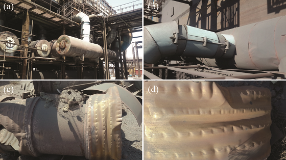
Note in Figure 3 (top) that there are several small cracks on the inner side of the sheet in the bellows that do not propagate toward other directions. Prior to the explosion, the pipeline controlling system did not record any increase of the gas pressure.
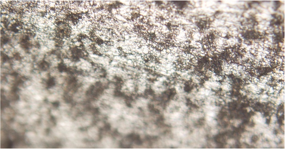
Figure 4 shows the optical metallography of the bellows. Polished samples were observed under a light-optical microscope to investigate crack-morphology. It is clear that martensite formed in the structure during the hot-working.3
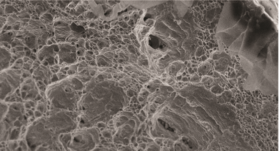
SEM analysis of crack surfaces at the edge positions was done. As can be seen in Figure 5, the origin of the crack initiation is the inclusions that are through the fracture surface.
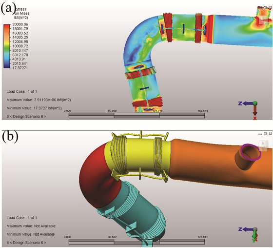
Figure 6 shows a schematic diagram of the working condition prepared using finite element modeling (FEM) with the mechanical simulation software. The models were meshed with mixed square and triangle elements. As can be seen in Figure 6, most pressures are in the metallic bellows and, as shown previously in Figure 3, many zones in the bellows are suitable sites for crack propagation.
Cracking due to the chemical corrosion is one of the main problems that may accrue and influences the service life behavior of the metallic bellows in the gas processing industries.3,9 H2S is one of the most corrosive agents for corrosion in the pipeline that generates hydrogen-induced cracking due to the reaction with the surface metallic bellows.3,5,9 The H2S penetrates into the metallic matrix and gathers at the interface between the martensite inclusions and dislocations, which then initiates cracking. This cracking mechanism usually occurs in wet H2S and takes place as an electrochemical process [Equations (1) through (3)].3
HS– + H+ → Fe (1)
Fe2+ + 2e → Fe (2)
Fe2+ + HS– → FeS + H+ (3)
Conclusions
In this study, a numerical simulation of the working condition of a pipeline carrying CH4 at 400 °C and the experimental investigations of the failure that occurred in the bellows were done. The following results are concluded:
• The simulated modeling results showed that during working conditions, the most stress due to the mechanical and thermal movement was in the bellows. So, these regions are expected places for cracks to initiate and spread.
• Optical micrographs show a great amount of martensite in the bellows expansion joint, which increases the material hardness.
• Wet H2S gas induces stress corrosion cracking that leads to crack initiation and nucleation due to distortion of the martensite and cold strain hardening. So, annealing treatment as a solution to remove the strain induced martensite and cold strain hardening is proposed.
Acknowledgment
The authors gratefully acknowledge the research and development of the Mobarakeh Steel Co. for the provision of research facilities used in this work.
References
1 F. Fantechi, M. Innocenti, “Chloride Stress Corrosion Cracking of Precipitation Hardening S.S. Impellers in Centrifugal Compressor,” Laboratory Investigations and Corrective Actions. Engineering Failure Analysis 8, 5 (2001): pp. 477-492.
2 N.W. Snedden, “Analysis and Design Guidance for the Lateral Stiffness of Bellows Expansion Joints,” Thin-Walled Structures 3, 2 (1985): pp. 145-162.
3 K. Guan, “Failure of 304 Stainless Bellows Expansion Joint,” Engineering Failure Analysis 12, 3 (2005): pp. 387-399.
4 H. Chen, et al., “Effect of Hydrogen-Induced Martensite on Stress Corrosion Cracking of Type 304 Stainless Steel in Boiling MgCl2,” J. of Materials Science Letters 21, 17 (2002): pp. 1,337-1,338.
5 J.H. Zheng, W.F. Bogaerts, “Effects of Cold Work on Stress Corrosion Cracking of Type 316L Stainless Steel in Hot Lithium Hydroxide Solution,” Corrosion 49, 7 (1993): pp. 585- 595.
6 C. Garcia, et al., “Effect of Prior Cold Work and Sensitization Heat Treatment on Chloride Stress Corrosion Cracking in Type 304 Stainless Steels,” Corros. Sci. 43, 8 (2001): pp. 1,519-1,539.
7 J. Kuniya, I. Masaoka, R. Sasaki, “Effect of Cold Work on the Stress Corrosion Cracking of Nonsensitized AISI 30 Stainless Steel in High-Temperature Oxygenated Water,” Corrosion 44, 1 (1984): pp. 21-28.
8 L. Huadonga, W. Weiqiangb, L. Yan, “Failure Analysis of a Bellows Expansion Joint of Inconel 625 Alloy,” Advanced Materials Research 500 (2012): pp. 580-585.
9 Q. Yuhai, L. Meishuan, Z. Yaming, “A Review on High Temperature Oxidation of Alloys under Mechanical Loading,” Corrosion Science and Technology Protection 13, 6 (2001): pp. 342-346.
10 EJMA Standard of the Expansion Joint Manufacturers Association, Inc., 7th ed. (White Plains, NY: EJMA, 2000).