In deep-water applications in the Gulf of Mexico, vibration-induced fatigue issues often arise due to wave-induced motion, vessel-induced motion, vortex-induced vibration, and/or flow-induced vibration.
A subsea vibration data logger (SVDL) can be installed directly on subsea equipment to monitor these and other forms of vibration and to assess fatigue. To protect the SVDL from corrosion in seawater, the system is electrically isolated from the main structure and aluminum anodes are connected to the SVDL body. Based on exposure time and seawater temperature, the size of the anode and its exposed area are important for protecting the SVDL components.
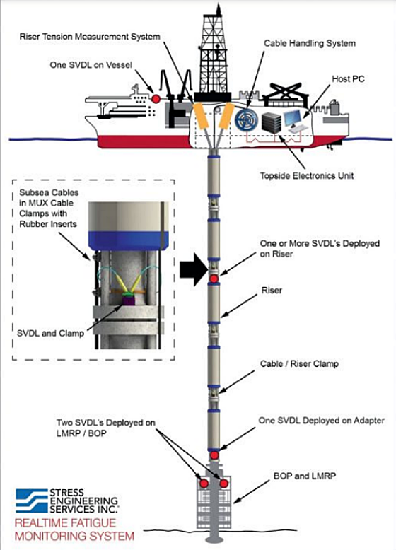
The subsea vibration data logger (SVDL) system1 is a purpose-built vibration monitoring system that is installed directly on subsea equipment to measure and record vibration data at a particular location and to then assess fatigue (Figure 1). The SVDL body is constructed from UNS S31603 (Type 316L stainless steel [SS]), UNS S32550 (super duplex SS), and nickel-aluminum bronze (NAB) UNS C63000. During service in seawater, the SVDL is protected from corrosion by attached aluminum anodes.
This study presents results from laboratory electrochemical corrosion testing involving galvanic current density (CD) measurements for various anode/cathode area ratios. The 1000 series aluminum anodes and three cathode materials, super duplex SS, Type 316L SS, and NAB, were studied. The laboratory tests were performed at two seawater temperatures, 4 °C and 24 °C, and three anode/cathode area ratios.
Galvanic CDs and corrosion rates from the testing indicated that aluminum anodes provide effective corrosion protection to super duplex SS and Type 316L SS. An equal-area aluminum anode was found to be sufficient to protect the NAB material at both temperatures. Test results also indicated that there is no significant galvanic effect between the NAB and super duplex SS
in the SVDL system.
In this study, laboratory electrochemical corrosion testing was performed to measure the galvanic CD using a commercially available 1000 series aluminum anode in combination with various cathodes, including SD255 super duplex SS, Type 316L SS, and NAB at two seawater temperatures and three anode/cathode area ratios.
Test Setup
Electrochemical galvanic corrosion testing was performed in accordance with ASTM G71-812 in synthetic seawater (ASTM D1141) using the anode and cathode materials previously described. All sample electrodes consisted of solid rods with the same surface finish (machined surface).
Tests were performed at two temperatures, 4 °C and 24 °C, under no- or low-flow conditions. Each test was performed for a total of 360 min. The potentials were measured using a saturated calomel electrode (SCE).
Test Results
Galvanic current and potential measurements at 4 °C and 24 °C are listed in Table 1 and Table 2, respectively. Relative CDs observed at an anode/cathode area ratio of 10:1 were not significantly higher than CDs observed at a ratio of 1:1. Aluminum (1000 series) coupled with SD255, at 4 °C and 24 °C, and aluminum coupled with NAB, at 4 °C, exhibited higher galvanic corrosion CD compared to aluminum coupled with Type 316L SS.
No significant galvanic corrosion was observed between SD255 and NAB. Similarly, no significant galvanic corrosion was observed between Type 316L SS and NAB.
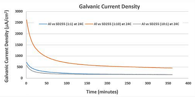
As expected, the galvanic CD was higher at 24 °C, indicating that sacrificial anodes, such as aluminum, are consumed more rapidly at ambient and warmer temperatures.5-6 Figure 2 shows a graph of galvanic CD of the Al/SD255 galvanic couple at three area ratios. These data show that a larger cathode consumes more sacrificial anode.
Galvanic anode corrosion rates were then calculated from the corrosion CD data
using Equation (1):
GCR=0.0033∙i∙EW/ρ
where GCR = galvanic anode corrosion rate in mm/year, 0.0033 = constant, i = CD in μA/cm2, EW = equivalent weight in g, and ρ = density in g/cm3.
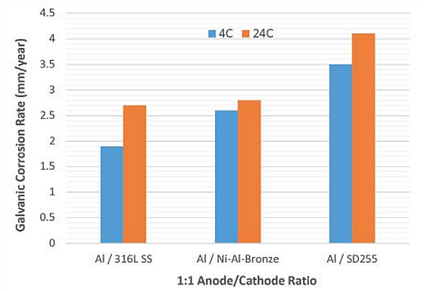
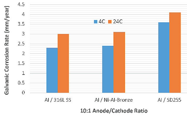
Calculated galvanic anode corrosion rates are provided in Table 3. Like the CDs, the galvanic corrosion rates of aluminum anodes were relatively higher at 24 °C with all three cathodes (Figure 3). With a higher anode/cathode ratio (10:1), the galvanic corrosion rates did not increase significantly compared to anode/cathode ratio of 1:1 (Figure 4). This indicates that larger anodes are preferable to protect the components.
Discussion
The effect of the relative areas of the anode and cathode on the rate of galvanic corrosion depends on the type of control in the system.7
If the galvanic system is under cathodic control, varying the anode area has little effect on the total rate of corrosion. The opposite is true if the system is under anodic control. On the other hand, the galvanic corrosion of aluminum changed only very slightly with an increasing aluminum anode area. These results indicate that the galvanic corrosion of the aluminum anode in this system is primarily cathodically controlled. Thus, larger sacrificial aluminum anodes are recommended in this scenario.
Galvanic currents in many situations are proportional to the surface area of the cathode. In this study, the galvanic corrosion of aluminum increased with a higher cathode (SD255).
Galvanic corrosion testing showed that there is no significant galvanic effect between SD255 and NAB. Similarly, no significant galvanic corrosion occurred between Type 316L SS and NAB. This outcome indicates that the galvanic effect does not influence the corrosion of NAB observed in seawater.
Conclusions
- Relative CDs measured at an anode/cathode area ratio of 10:1 were not significantly higher than the currents measured at an anode/cathode area ratio of 1:1.
- Aluminum anodes (1000 series) coupled with SD255, at 4 °C and 24 °C, and aluminum anodes coupled with NAB, at 4 °C, exhibited higher galvanic corrosion CDs compared to aluminum coupled with Type 316L SS.
- No significant galvanic corrosion was observed between SD255 and NAB. Similarly, no significant galvanic corrosion occurred between Type 316L SS and NAB.
- Test results indicate that the galvanic corrosion of the aluminum anode in this system is primarily cathodically controlled. Thus, larger sacrificial aluminum anodes are recommended in this scenario.