Cathodic protection (CP), when properly applied, is an effective technique to minimize the natural corrosion process that occurs on pipelines, tanks, and other buried steel structures. Corrosion professionals are responsible for maintaining effective CP coverage with minimal current demand and delivering an efficient and effective system.
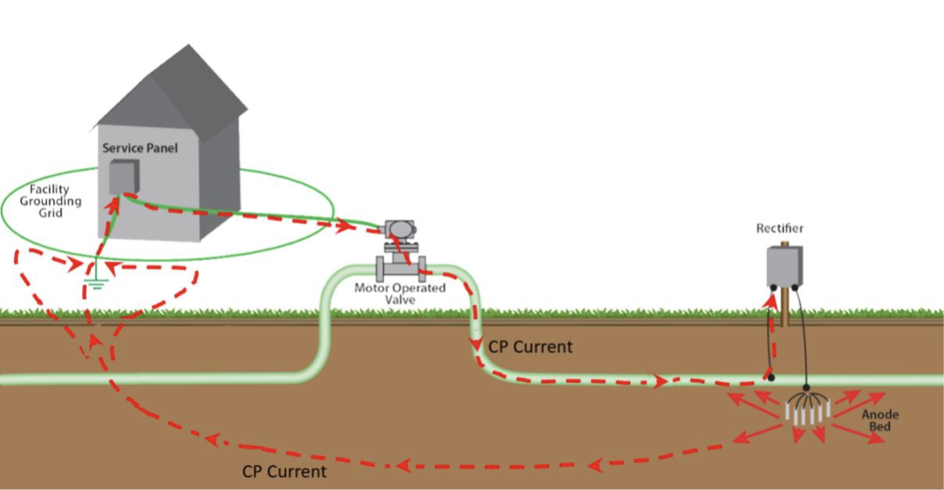
However, these structures require electrical grounding for both personnel safety and protection of the structure from damage due to over-voltage conditions. Grounding systems for AC mitigation systems, AC fault and lightning protection, and electrical equipment protection all introduce undesired paths for CP current to return to the rectifier by way of the structure.
This requires the CP system to protect significantly more material surface area for which it was not designed. As a result, a corrosion professional may have difficulty maintaining adequate CP potentials on the structure without significantly increasing costs generating higher levels of CP current.
Corrosion professionals must be aware of these competing requirements, optimizing their CP system while simultaneously providing necessary safety grounding.
The Challenge with Grounding Systems

CP systems, and external corrosion protection in general, require that the structure be electrically well-isolated. Since CP systems are designed to protect only relatively small defects in the coating of the protected structure, the degree of isolation determines the efficiency and effectiveness of the CP system in protecting the structure.
Certainly, the less surface area of the structure that is directly in contact with earth, the less CP current is required for protection.
Additionally, every surface on the structure that interfaces other grounded structures must be insulated to minimize CP current flow through the other structures. This is accomplished using isolation kits and monolithic joints at piping connections, dielectric fittings for smaller piping connections, conduit and sensor connections and isolation pads for aboveground pipe supports.
In addition to these mechanical interfaces, there are electrical connections between the structure and the grounding system for which continuity must be maintained to protect the structure and personnel from potential over-voltage conditions. These connections include safety grounding for AC mitigation systems and protection from AC faults and lightning for electrical equipment.
Use Solid-State Decouplers to Optimize Your CP System
When faced with insufficient CP potentials due to such required earthing bonds, CP designers might be inclined to add more rectifiers and anode beds and tolerate high CP current demand. However, this is likely a prohibitively expensive option and may ultimately not provide sufficient protection.
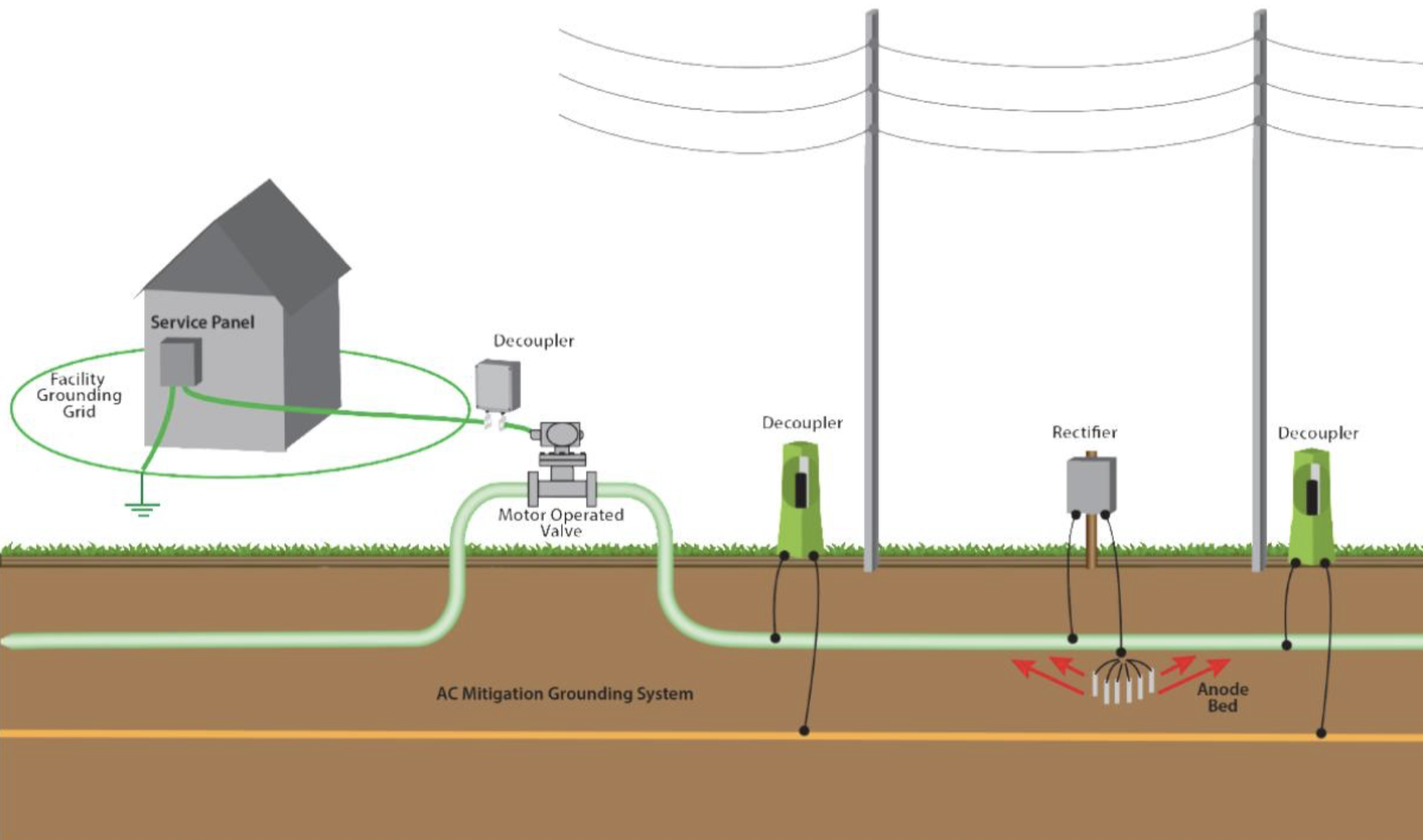
Instead, corrosion professionals have widely accepted a solution that can provide safety grounding while also optimizing CP system performance. Installing DC decoupling devices in series with the bonding connections between the cathodically-protected structure and the grounding system as shown in Figure 2.
This prevents CP current from passing through the grounding systems and so minimizes the amount of CP current required to protect the pipeline. As a result, corrosion professionals can simultaneously offer safely grounded system, and an efficient and effective CP system.

Requirements of Solid-State Decouplers
Decoupling products must be selected with careful examination of their electrical characteristics relative to the intended purpose in order to assure proper application. Solid-state over-voltage protectors use high-power, solid-state electronic switching components to create a switch between the two structures to be isolated.
Under normal conditions, this switch remains open, maintaining DC isolation between the structures. When the differential voltage across the terminals exceeds a prescribed voltage threshold, which would occur during a fault or lightning event, the switch closes virtually instantaneously, collapsing the voltage across the terminals and electrically bonding the structures. Immediately following the over-voltage event, the device then automatically switches back into the OFF state to maintain DC isolation.
Solid-state decouplers, in addition to bonding structures during AC faults and lightning, provide a continuous conduction path for steady-state AC to pass through the device at all times. By shorting steady-state-induced AC current, a solid-state decoupler reduces AC voltage on the pipeline and prevents the AC voltage from triggering the solid-state switch.
Corrosion professionals must also factor in several device characteristics to ensure proper device performance.
Low Impedance for AC Faults and Lightning
One of the most basic requirements of decoupling devices is to provide a low impedance path for AC faults and lightning. During such an event, the voltage across a solid-state device clamps at the threshold voltage, which is typically 3 volts or less. Under the most extreme AC fault conditions, the maximum voltage across the terminals is less than 10 V.
Under lightning surge events, this maximum voltage is approximately 100 V. This assures that over-voltages will be clamped to low levels during faults or lightning events, providing a significant advantage for personnel safety and for applications such as isolated joint protection.
Sufficient Device Ratings
Typical AC fault current exposure on pipelines near HVAC towers is 5 kA, and levels up to 15 kA are not uncommon. Reliable solid-state devices have the ability and ratings to handle AC fault current at these levels.

Low Impedance for Steady-State AC
To be effective for use as part of AC mitigation systems, decoupling devices must be able to continuously conduct steady-state-induced AC. This includes devices used across isolation joints if earthing points on the opposite sides of the joint are part of the same AC mitigation system.
Solid-state decouplers continuously conduct steady-state AC, and most introduce only a few milliohms of impedance and so do not significantly affect the pipeline voltage.
Low-Maintenance and Fail-Safe Design
Given the remote location of many pipelines, low maintenance and reliability of decoupling devices is extremely important to most corrosion professionals. Product reliability, performance, and required maintenance should be factored into material selection practices. Current-generation decoupling devices typically consist of solid-state components, requiring no maintenance.
Corrosion professionals should verify with manufacturers so they can be assured of expected performance lifespan and maintenance requirements and factor that into their selection process.
Products should also be designed with fail-safe construction. If exposed to fault current values beyond their ratings, devices should always fail safely and uneventfully in the shorted mode (fail as a dead-short), bonding the two points together for safety. This assures that over-voltage conditions will be addressed—whether the product is working or failed. Most modern solid-state devices are considered truly “fail-safe” and corrosion professionals should review and verify independent third-party product certifications to be sure of this important safety characteristic.
Low DC Leakage Current
To maintain the efficiency of CP systems, it is important to minimize DC current leakage to earth through decoupling devices. Since many modern pipeline coatings provide such effective isolation, CP rectifier currents are often so low that several milliamps of DC current loss to earth through a decoupling device can negatively affect CP performance.
Solid-state decouplers, when properly applied within the threshold voltage range, typically have less than 10 mA DC leakage. Product performance should be readily available from the manufacturer.
Hazardous Location Ratings
Corrosion professionals may often oversee sites that are formally classified as hazardous locations, as defined by international standards such as the International Electrotechnical Commission (IEC) according to the concentration of flammable gases or liquids present.
Electrical devices must meet certain design and quality requirements to be used in these locations. If a site is classified or otherwise treated as a hazardous location, then the material selected in these locations must hold third-party certifications (UL, ATEX, IECEx) stating the environment in which they may be used.
Conclusions
To minimize corrosion, pipelines and storage tanks rely on expensive coatings, isolation joints, and cathodic protection systems to isolate the structure from the earth. However, to mitigate the damaging and hazardous effects from AC interference and lightning, these structures require intentional earthing systems.
These conflicting requirements have been addressed, in general, by the widespread use of DC decouplers. Decouplers, when installed in electrical connections between CP-protected pipelines and earth, provide both DC isolation and bonding for AC and lightning.
However, not all DC decoupling devices are created equal. For example, spark gap devices should not be used for most applications located near HVAC power lines since they do not pass low-voltage, steady-state-induced AC to earth and they are not properly rated to handle AC faults levels that are typically observed on pipelines in these locations.
In addition, many DC decouplers have not been well validated by reputable third-party certification agencies to meet stated performance criteria. It is important to thoroughly understand the performance strengths and limitations of the devices before application.
Editor’s note: This article first appeared in the May 2023 Cathodic Protection Supplement of Materials Performance (MP) Magazine. Reprinted with permission.