This article discusses methods to evaluate the corrosion of substrates and breakdown of protective coatings subject to wet-dry cycling in natural and accelerated environments. Principally, the discussion concerns the ability to monitor on-going corrosion deterioration to predict coating failure in a real-world environment without having to accelerate (i.e., artificially harshen) the environment.
The author previously introduced a method to evaluate protective coatings using a novel segmented cell approach.1 Briefly, the technique intended to monitor natural current exchange between isolated segments, coated or uncoated, to supplement visual rankings of coating performance.
The goal was to predict failure earlier than might otherwise be visible or to distinguish between coatings that had a similar visual appearance at the end of the proscribed test period.
The experimental design also allowed for the instrumented segments, which act as sensors, to be prepared and coated as intended for a real-world industrial exposure where the metallic surfaces could be abrasive blasted and painted, unlike thin film. Foil-like sensors were also explored for similar purposes. The initial work focused on the type of data that might be obtained and demonstrated the utility of the approach.
This testing included longer-term data, wherein the segmented cell approach was used to study coatings intended for immersion service. Testing for immersed conditions allowed the inclusion of a continuous water film across the coating surface, simplifying the testing and data analysis. Testing under atmospheric conditions was limited at the time. The present work expands on these earlier presentations.
Experimental Approach

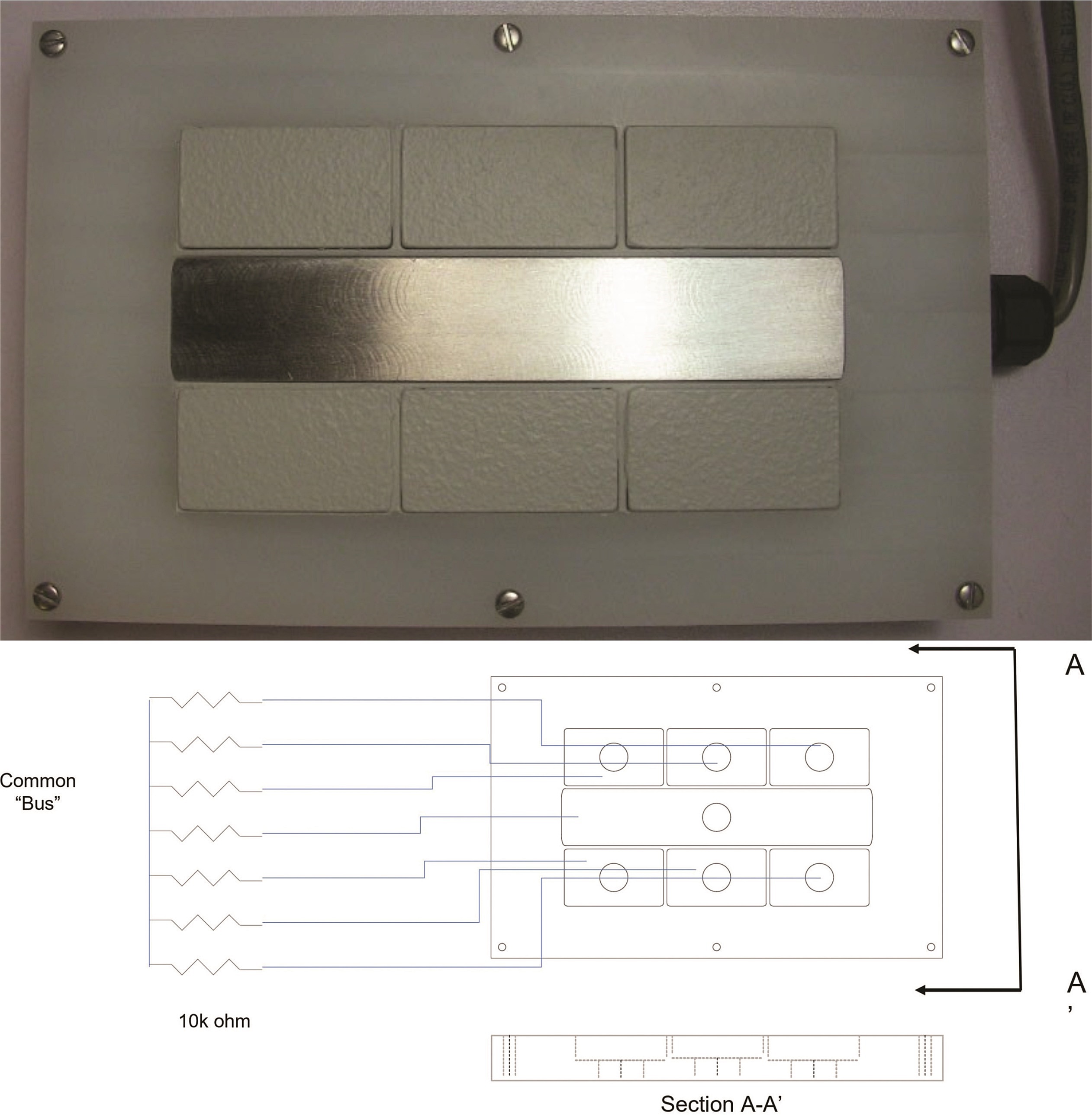
Figure 1 provides a plan-view photograph of a segmented-cell design. The design includes seven elements. Each is nominally 0.6 cm thick. The center segment is nominally 14 cm long and 2.5 cm wide. For some testing, the center segment was 0.6 cm wide; this difference related to fabrication issues and was not deemed significant in the data generated. The outlying six segments are nominally 4.4 cm long and 2.5 cm wide.
Previous designs cast the segments into an epoxy resin. The present improved design includes a non-metallic face fabricated to hold each segment. The face comprises one side of an enclosure. The entire system may be reused with the application of new coatings or the use of new coupons, reducing the overall system cost. In the work discussed herein, the center segment is always left uncoated, intending to function as a “scribe” or intentional holiday in a coating system.
Coatings are applied to the surrounding segments using conventional surface preparation and coating application procedures. The individual surrounding segments can be abrasive blasted before being installed into the coupon holder. Paints are applied after the coupons are installed with the center segment suitably masked.
Each segment has a lead wire connected to its base. The seven leads comprise a cable bundle that leads outside the box via a water-tight compression fitting. The box top to base closure includes an O-ring groove and a Viton† gasket. The lead wires carry signals to an electronic data acquisition (DAQ) system.
At the DAQ, the peripheral segments are connected to the central segment across 10,000-ohm shunt resistors (Bourns 4100R Series,† 2% tolerance), thus forming a pseudo-parallel circuit. Voltages at the shunts are read via a gang of NI 9205, C Series Voltage Input Modules.† These are 16-bit A-to-D devices.
Data were captured via a custom LabView† program. Current data were captured every five minutes. These are the net anodic and cathodic currents between these segments.
There can also be local anodic/cathodic reactions on each sample that are not represented. Algebraically, the total current is “zero.” With “fully intact” coatings, the shunt resistor does not dominate the current exchange. As a coating would degrade, the shunt may impact the current more significantly.
For the data presented herein, all the exposures concern samples placed into a natural atmospheric environment, urban Northern Virginia, and subject to a periodic wetting with a substitute seawater solution to stimulate corrosion. Various coating systems are discussed as presented. The focus is on the cell performance, not the coating per se.
Results

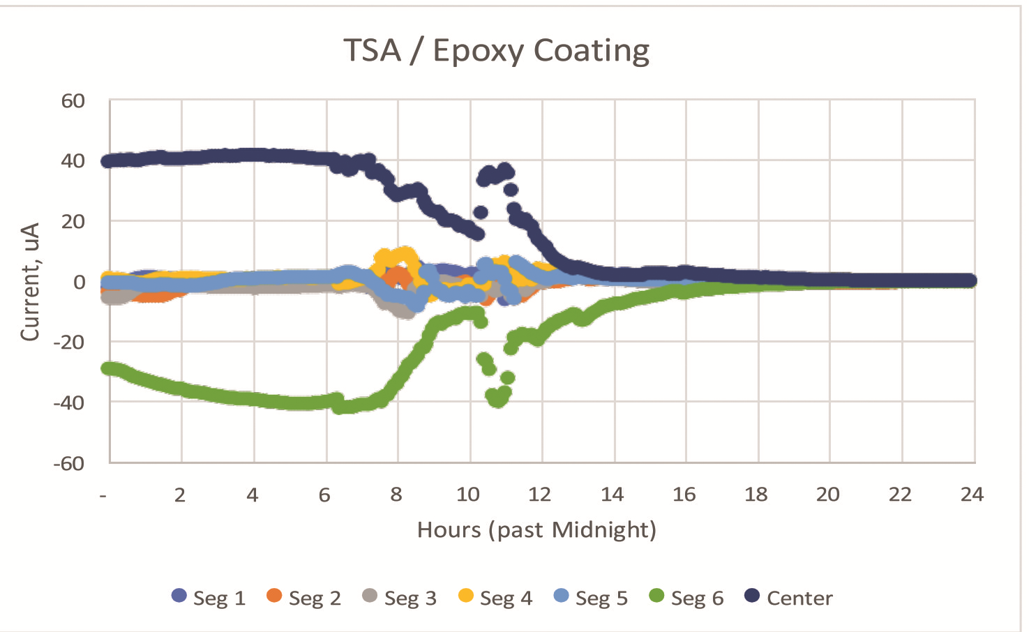
Figure 2 shows the current exchange at 5-min intervals for a thermal-spray aluminum coating applied to steel and coated with a nominal 0.15-mm (6-mil) thick epoxy seal coat. Negative currents indicate anodic behavior.
Given the significant electrochemical potential difference between the active thermal spray coating and the steel center scribe, this example provides a good basis to establish an understanding of the impact of the local environment.
In Figure 2, the primary source of current is segment 6, with the other five segments providing significantly less current at nominally five days of exposure.
Figure 3 shows the center segment alone, plotted with the local relative humidity (RH) and temperature on this day. The correlation with humidity is clear and aligns with the common understanding of the tendency for surface salts, such as sodium chloride (NaCl), to deliquesce moisture from humid air. In the data, as the humidity transitions from above 80% RH to below 40% RH, the current drops close to zero amperes. Figure 4 presents data for this same test cell for the first 30 days of natural exposure.
The current plotted daily is the average value over the 24-h period. Over time, the initial current decreases as might be expected in part from the formation of corrosion products. Among the coated segments, the current from segment 6 (days 4 through 8) and segment 1 (days 6 through 16) stand out from the r samples as the most active areas.
Figure 5 provides a similar dataset for an epoxy/urethane coating applied directly to steel, with current exchange to a central scribe. The exposure again is a natural environment with daily wetting with artificial seawater. The magnitude of current in this cell is nominally 10X less than with the thermal spray aluminum applied to steel, as might be expected.
In the present cell, the current exchange is created by the anodic behavior of the coated steel vs. the boldly exposed central scribe and anodic undermining of the coating. At about day 50, segments 4 and 5 began to exhibit the most significant anodic currents. In days 80+, segments 4 and 5 seem joined by segment 2.
Figure 6 shows a view of segment 5 alone, adjacent to the scribe, at different times in the exposure. At day 50, when the current at segment 5 begins to be more anodic than the remaining segments, there is no readily apparent visual clue that the coating is deteriorating. After 100 days, a blister and crack parallel to the scribe becomes visually apparent.
Figure 7 shows the test panel following removal of coating suffering from creepage damage and blistering of the coating. The physical damage at segments 2, 4, and 5 with minor damage at 6 correlate well with the observations from the current data.
The low currents and lack of damage at segments 1 and 3 also correlate. The area of blistering, anodic undermining, and a cathodic delamination front beyond the anodic undermining are clearly observable.
Conclusions
- A segmented cell approach offers a viable method to study the performance of protective coating systems applied over a variety of metallic substrates. The current exchange data offer insight into the protective properties of the coating system prior to the onset of any visual indication and may provide critical data on coating performance without the confounding concerns over the effects of an accelerated environment.
- The currents can vary as a function of the local environment, absent any changes in the coating. Developing such relationships may allow one to extrapolate the present results to other exposure environments via comparison of the magnitude and frequency of different exposure environments.