If the reinforcement design and the concrete mix design are appropriate, then a concrete beam will exhibit acceptable behavior during a bending test. The flexural strength of the concrete beam results from a combination of tensile strength from the reinforcement and compressive strength from the concrete. The bending test of the concrete poles was performed according to an Iranian instruction test for concrete poles.1
Therefore, it is first necessary to explain the test. It is similar to the bend test described in CEB Standard 044-3;2 the two tests are almost the same, yet slightly different. In the Iranian test, the part of the concrete pole that is placed in the ground is marked. The length is ~14% of the total length of the pole. This area, according to Figure 1, is firmly fixed between two strong reinforced concrete abutments.
In concrete poles with an H cross-section (as in Figure 1), the beam is placed in such a way that the full web of the H section faces upward. Bend force is applied at a distance of 60 cm from the tip of the beam (as shown in Figure 1). Also, at a distance of 3 m from the end of the concrete pole, a bed of roller tracks is used to allow easy lateral movement of the pole during the application of bending force.
According to Figure 1, before applying bend force, a metal vertical marker is in contact with the pole. During the application and removal of force, the amount of deviation of the pole from the metal marker is measured and recorded.
A five-ton puller machine is used to bend the pole. Bending force is transmitted to the pole by means of a steel chain or steel cable. Also, for measuring applied force, a dynamometer is used near the location of applying force to the pole. The other end of the steel chain or steel cable is fixed to a stable, strong, and firmly positioned anchor, as shown in Figure 2.
In the bend test, three results can be obtained, including normal, elastic behavior, and ultimate bending strength of the concrete pole.
 Dynamometer for measuring bending force, and (b) the other end of the steel puller chain is fixed in a stable and strong position.")
Normal Strength
Every concrete pole design has a specific normal bending strength. Admittedly, the normal strength is within the elastic range of the concrete beam and is much lower than the yield bending force of the concrete pole. In this test, at first, details of the concrete pole surface, including surface or deep cracks and other defects observed on the concrete surface, are recorded.
Then, four steps are performed in which the bending force is increased slowly up to 0.25 of normal strength for each step. The location change of the concrete pole tip from the vertical marker and surface defects and other effects are recorded at each step. In other words, during the first, second, third, and fourth bending force step, without removing the previous bending force, an increase up to 0.25, 0.50, 0.75, and 1 of normal force strength on the concrete pole is performed, respectively. Finally, the load is slowly and completely removed and the permanent displacement of the concrete beam from the marker and other defects are reported.1
If the concrete pole has the desired flexural strength, then first, it does not crack at any of the application bend force steps; second, the curve of displacement of the concrete pole tip vs. the applied force in all four steps are linear; and third, after removing the bend force, the pole returns approximately to its original state and no cracks are observed, except very small cracks called “hair-like cracks.” If the concrete pole does not meet the three mentioned requirements, it will not have the design-required normal strength. This weakness will become more apparent in subsequent tests, including elastic behavior and ultimate force strength tests, which is explained further in the next section.1
Elastic Behavior
Concrete poles are designed to withstand a bending force equal to 1.5 times the normal bending force without falling out of the elastic range. In this test, the force applied to the concrete pole slowly increases to the level of normal strength and the position of the concrete pole tip relative to the marker and all created defects are recorded. Then, the following steps are applied on the concrete pole, including:
1. The applied force is slowly increased up to 1.25 of normal strength force and the position of the pole tip relative to the marker and created cracks and their exact position are recorded.
2. The applied force is slowly reduced to the normal strength force level and displacement of the pole tip and remaining cracks are accurately recorded.
3. The applied force is slowly increased up to 1.50 of normal strength force and similar to the previous case, the displacement of the concrete pole tip and the location and number of cracks are accurately recorded. During this step, oblique cracks may appear in the center area of the concrete pole.
4. The applied force is slowly reduced to normal strength force and the amount of displacement of the pole tip relative to the marker and remaining cracks are recorded.
If the concrete beam is destroyed during the elastic test phase, then the concrete pole is completely rejected, but if it is not destroyed, it must meet the following three conditions to be acceptable:
1. Cracks are closed by reducing bending force and reaching normal force.
2. During application bending force, the displacement of the pole tip relative to the marker must be proportional to the bending force, or in other words, its curve must be a straight line.
3. After removing all forces, the displacement of the pole tip should not be >10% of the displacement of the pole under a flexural force equal to 1.5 times the normal force.1
Ultimate Bending Strength
In this test, an initial bending force equal to 125% of normal strength is applied to the concrete beam and the displacement of the pole tip and the number and location of created cracks are recorded. Then, the bending force is increased in a few steps at a rate of 25% normal resistance until the pole tip reaches a point that continues displacement without adding additional force and this force is taken as the ultimate bending strength of the concrete pole. At each step, the number and location of the created cracks are recorded.1
In poles with normal strength up to 400 kg, ultimate strength must be at least three times the normal strength, and in poles with normal strength more than 400 kg, ultimate strength must be at least 2.5 times the normal strength.
Results and Discussion
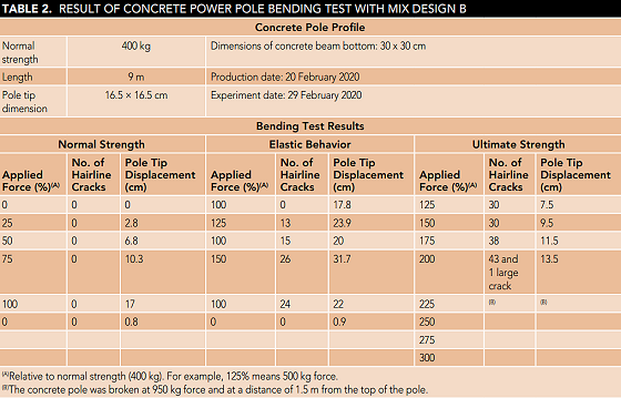
In this study, two concrete power poles that are the same in terms of reinforcement design, but different in terms of concrete mix design, are tested for bending. In our previous article,3 laboratory tests on two types of concrete mix designs were described, and in this study, the same previous mix designs were used in the construction of two concrete poles used in the bending test. The average compressive strength of the first (A) and second (B) concrete mix designs after 8 h of moist curing was 517.5 and 295 kg/cm2, respectively. The poles were moist cured for 8 h and then placed in a water pool for three days.
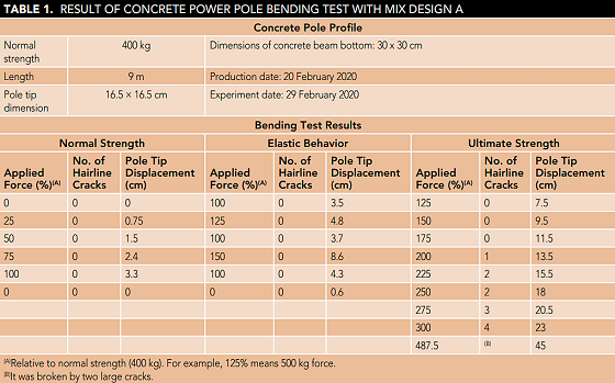
The results of the bending tests of concrete pole (A) and (B) are presented in Tables 1 and 2, respectively.
According to Table 1, concrete pole A has suitable bending strength. It failed at 1,950 kg load, which is equal to 487.5% of normal strength (more than three times its normal strength). Therefore, pole A is expected to have good durability in field conditions. It has the necessary resistance against mechanical forces and its concrete has suitable compressive strength. As a result, it has suitable density to impede penetration of corrosive agents into the pole.
According to Table 2, pole B did not have large cracks in the normal strength and elastic strength test and only a few small cracks. The displacement of the column tip after removal of the normal load was not zero but 0.8 cm. According to Iran’s Instruction Standard for testing concrete power poles, final strength of concrete poles must be three times normal strength. Pole B failed at 950 kg force, which is lower than three times normal strength (1,200 kg). Therefore, pole B was rejected in the bending test, and it is not expected to have suitable durability in field exposure.
Conclusions
In field conditions, the mechanical forces applied to the concrete columns can cause cracks in them and accelerate the penetration of corrosive agents into the column. If the concrete used in the column has high compressive strength, first, the concrete column has a high resistance to the penetration of corrosive agents, and second, in field conditions, it resists against mechanical forces and does not suffer from cracking, corrosion, and concrete collapse. Therefore, a bending test is a good criterion for predicting the durability of concrete columns in environmental conditions.
References
1 Iran’s Instruction Standard for Testing Concrete Power Poles (Pre-Tensioned and Non-Pre-Stressed).
2 CEB Standard 044-3, “Acceptance Test of Concrete Poles” (Colombo, Sri Lanka: Ceylon Electricity Board, 1966).
3 A. Aghajani, B. Aghajani, “Control of Environmental Degradation of Concrete Power Poles,” MP 57, 11 (2018).