Vehicular braking events are a phenomenon that converts kinetic energy into heat. In a disc brake system, this occurs as the result of a friction force between two braking pads that are pushed against opposing sides of a rotor by means of a caliper, thus generating the braking torque (Figure 1).1
In the case of high-end cars or motorbikes, the caliper body is most often an aluminum-silicon alloy. Furthermore, a large number of components with different corrosion potentials are also typically included.2 The brake disc is typically fabricated from cast iron (cars) or stainless steel (motorbikes) or, more recently, using coated cast iron solutions.3 The braking pads are composed of friction material (FM) that can be considered as a composite, including abrasives, solid lubricants, metallic powders, or fibers and organic binders.4
Thus, it appears clear that all the materials comprised in a braking system can easily generate galvanic couplings and undergo severe corrosive phenomena once exposed to aggressive conditions and harsh environments.5-7 For these reasons, effective protection strategies are needed to ensure that the functional and safety properties of the braking device are retained, even when facing such demanding conditions.8
In particular, considering the operating conditions of a car, and consequently of its brakes, several corrosion-inducing environments can be encountered, including, for instance a) contact with chloride-based road deicer during the winter time; b) exposure to NOx and SOx in the case of heavy traffic conditions; and c) contact with surfactants upon car washing.6
Among all possible corrosive phenomena, those that involve FMs are particularly important. For example, shear adhesion events (also known as sticking effect) with the cast iron disc, especially after prolonged parking, can be associated with the growth of corrosion products at the pad-disc interface and can lead to a physical bonding of the two components.9-10 The following discussion presents the characterization of corrosion scales that are present on the surface of a reference FM upon exposure to different corrosive atmospheres.6
Experimental Procedures
A detailed description of the experimental methods and materials can be found in recent literature6 and summarized as follows.
The reference FM is a prototypal formulation with the main components consisting of S: 7.0 wt%, Cr: 4.4 wt%, Zn: 21.7 wt%, and Fe: 24.7 wt%. Linear sweep voltammetry measurements in a) 5 wt% potassium sulfate (K2SO4(aq)); b) 5 wt% sodium chloride (NaCl(aq)); and c) 1 M sulfuric acid (H2SO4(aq)) are performed using a potentiostat/galvanostat to evaluate and mimic the corrosion performance of the proposed friction material in different corrosive environments. Measurement details are as follows: scan rate = 0.5 mV/s; temperature = 30 °C; reference electrode: saturated calomel electrode; counter electrode: graphite rod; and working electrode: FM under investigation with known geometrical area.
Corroded FM specimens are obtained after a 360-h climate chamber exposure to the following corrosive atmospheres: a) 100% relative humidity (RH); b) neutral salt spray test solution (NaCl(aq) 5 wt%) in agreement with ISO 9227:2017;11 and c) acidic spray test (H2SO4 1 M). These three different aggressive atmospheres are aimed to simulate 1) heavy rain condition; 2) presence of deicing agents (e.g., chloride-based road salt); and 3) heavy industrial and polluted conditions, respectively.
The resulting specimens, after exposure to the previously mentioned corrosive atmospheres, are characterized using a multi-technique approach, including confocal microscopy, scanning electron microscopy (SEM), x-ray fluorescence, Raman spectroscopy, and x-ray diffraction (XRD). The main results are discussed in the following paragraphs.
Results and Discussion
Corrosion Performance
Electrochemical techniques are fundamental methods to evaluate the corrosion resistance of several bulk materials and coatings used in braking systems. They can include conventional aqueous electrochemistry-based methods, as well as advanced impedance or zero resistance ammeter-based experiments. An in-depth electrochemical characterization of braking system materials allows not only to investigate the corrodibility of pristine materials, but also to evaluate possible galvanic couplings and to propose design rules based on selected electrochemical figures of merit.3,5-9

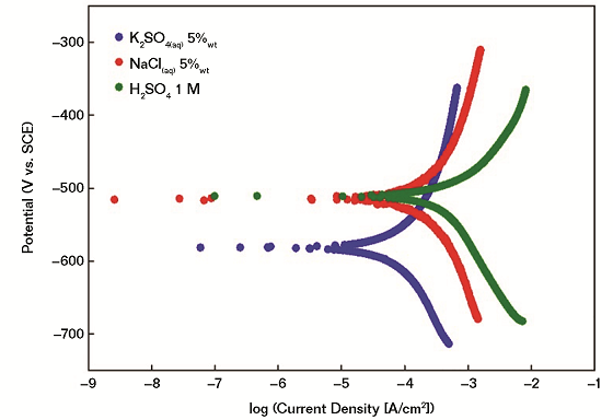
With particular reference to this work, linear sweep voltammetry measurements are performed in order to evaluate ex-situ the corrodibility of the proposed FM in different corrosive environments. Measurements are performed using three different electrolyte solutions, namely K2SO4 (aq) 5 wt%, NaCl(aq) 5 wt%, and H2SO4 1 M (Figure 2).
It is demonstrated that the investigated FM has a higher tendency to undergo oxidation in (SO4)2– rich environments (e.g., 5 wt% K2SO4) even if the highest corrosion current and, thus, corrosion rate, is obtained in the case of acidic conditions (1 M H2SO4). In all cases, electrochemical measurements confirm that a) the main corrosive event is associated with the iron oxidation in different environments; and b) local pH values are playing a major role in modulating the corrodibility of friction materials. It is expected that the differences in the corrosion performance would be reflected in the formation of different corrosion scales whose careful investigation is described in the following sections.
Imaging Techniques
Visual inspection of the corroded FMs after exposure to corrosive environments can be performed using optical and/or electronic microscopes.6 These two techniques can easily reveal the presence of corrosion products and their spatial extension.12 In the case of the proposed FMs, both SEM and optical microscopy synergistically allow obtaining the following main conclusions (Figure 3):

1) In the case of 100% RH exposure, corrosion products are mainly localized in close proximity of iron fibers.
2) In the case of 5 wt% NaCl exposure, the concentration of corrosion products is generally higher and different color domains can be identified and associated with different iron oxihydroxides polymorphs.
3) In the case of H2SO4-rich atmospheres, corrosion products are localized in close proximity to iron fibers and consist of iron sulfate crystallites.
It is important to highlight that imaging techniques can easily distinguish between different kinds of corrosive phenomena, such as localized or diffused corrosion, as well as the presence of crevices or pits.
Raman Spectroscopy and XRD Measurements
Raman spectroscopy and XRD are key techniques to investigate the structure of crystalline solids. They can be used to a) identify crystallographic phases within a material; b) perform quantitative phase analysis and relative abundance considerations; and c) evaluate the crystallinity degree of materials with a certain long-range ordering. In the case of µ-Raman measurements, a microscope is coupled with a Raman spectrometer, thus directly focusing the laser beam on the site of interest and obtaining a spatial resolution as high as 1 µm. Moreover, µ-Raman appears as a particularly useful in-situ probe to map the phase distribution of scales in close proximity of corroded areas, including pits and crevices.12-15
When applied to corrosion science, XRD and µ-Raman techniques allow a quick and diagnostic identification of corrosion products by comparing the experimental patterns with suitable crystallographic databases.

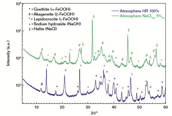
In the case of the investigated FM, both µ-Raman spectroscopy and XRD concur in achieving the following conclusions (Figure 4):
1) Corrosion scales obtained from the exposure to 100% RH are mostly associated with three iron-based oxyhydroxides, namely a) lepidocrocite (γ-FeOOH); b) goethite (α-FeOOH); and c) akaganeite (β-FeOOH), with the latter being detected in traces only. As a qualitative consideration, the crystallinity degree of the three oxy-hydroxides can be defined as moderate in agreement with the full width at half maximum of the measured diffraction peaks.
2) In the case of salt spray exposure (5% NaCl), a completely different phase distribution is revealed, with the akaganeite polymorph being the most abundant phase, while lepidocrocite and goethite are present only in traces. At a deeper level the crystallinity degree of the akaganeite phase appears as particularly low and, thus, associated with broad diffraction peaks. In agreement with the literature, the presence of β-FeOOH can be considered as a marker of an aggressive corrosion process that briefly leads to the formation of highly oxidized iron-based species, such as magnetite and/or maghemite.
Conclusions
This article demonstrates that the corrosion of FMs included in a braking system can lead to a wide range of different corrosion scales, mainly depending on the nature of the aggressive environment at which they have been exposed. Characterization of the obtained corrosion products plays a major role in a) clarifying the corrosion-based failure mechanism; and b) proposing effective solutions to extend the corrosion resistance of future braking systems.
A clear correlation between the nature of the corrosive agents and the composition and structure of the obtained corroded FMs is elucidated using a multi-technique approach. It is demonstrated that the exposure of the FM to a 100% RH atmosphere leads to a diffused presence of small goethite and lepidocrocite crystallites on its surface. On the contrary, exposure to a salt spray solution is responsible for the presence of akaganeite domains with very low crystallinity degree. Finally, the exposure to sulfuric acid vapors induces the formation of hydrated iron sulfate-based products in correspondence of metallic fibers comprised in the FM.
Taken altogether, it can be concluded that a) corrosion products present on the surface of the considered FM are always associated with iron oxidation; b) corrosion by-products are strongly linked with each investigated corrosive environment; and c) corrosion scales can be identified by a coupled evaluation of their spatial distribution, composition, and morphology.
References and About the Authors